3. Remove the key from the instrument panel
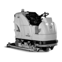
4. Loosen the knobs (2) and (3) in the squeegee pre-assembly
5. Insert the left-hand squeegee pin in the left-hand slit of the squeegee connection, then tighten the knob
(2), making sure the washer and spring adhere in the upper part of the squeegee support
6. Insert the right-hand squeegee pin in the right-hand slit of the squeegee connection, then tighten the
knob (3), making sure the washer and spring adhere in the upper part of the squeegee support
7. Insert the vacuum hose (4) in the squeegee sleeve
ATTENTION: these operations must be carried out using protective gloves to
avoid any possible contact with the edges or tips of metal objects.
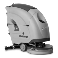
23. ADJUSTING THE SQUEEGEE INCLINATION
During working operation, the rear rubber is slightly tilted backwards (by about 5mm) in a uniform way for
its whole length. If you need to increase the bend of the rubber in the central part, you must tilt the
squeegee unit. To do this, proceed as follows:
1. Loosen the locknut (1)
2. Turn the screw (2) clockwise to increase the bend of the rubber in the central part of the squeegee.
3. When fully adjusted, fix the locknut (1)
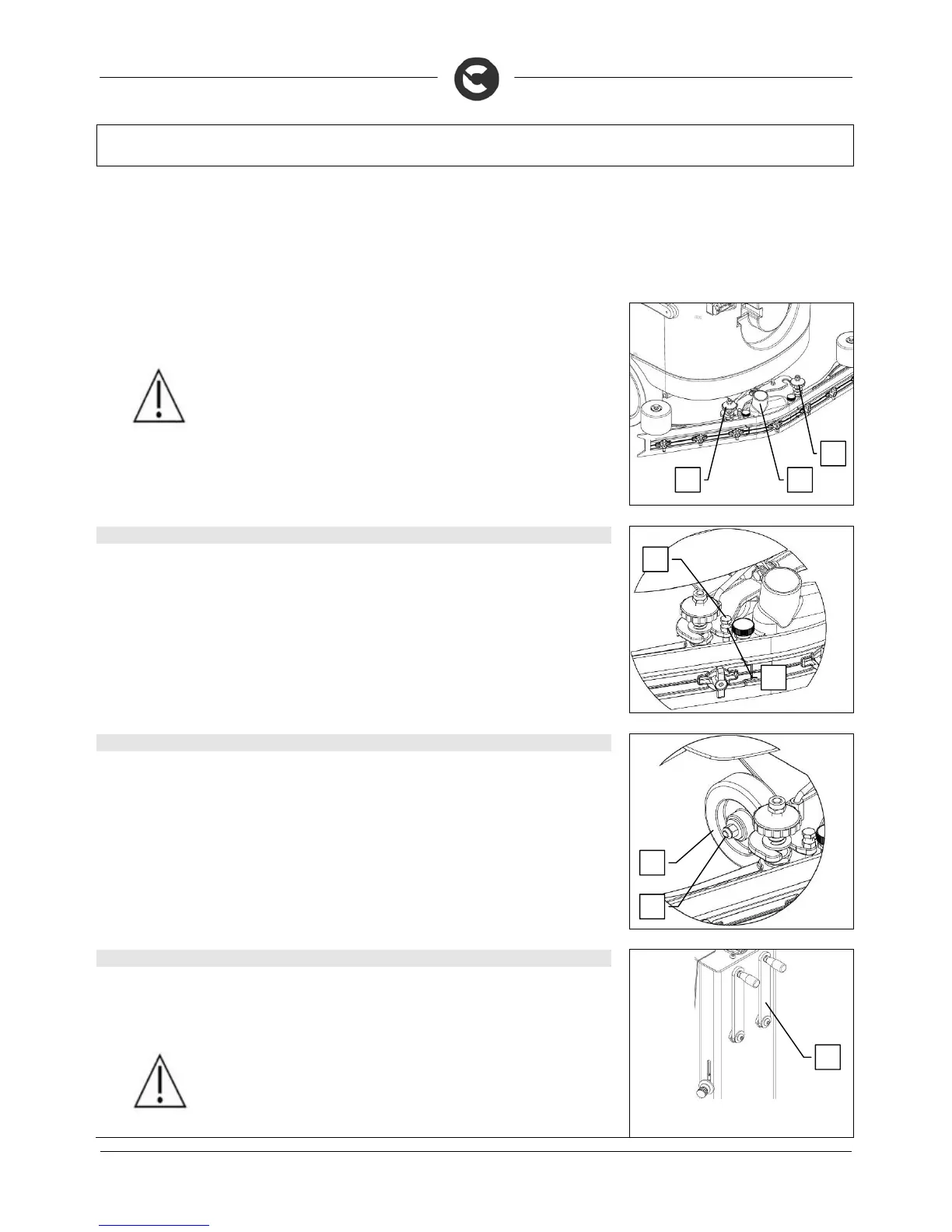
24. ADJUSTING THE SQUEEGEE HEIGHT
The height of the squeegee must be adjusted on the basis of the state of wear and tear of the rubber.
Carry out the following operations for adjustment:
1. Loosen the locking nuts (1)
2. Raise or lower the wheels (2) by sliding them in the slot on the squeegee support
3. Block it by tightening the locking nuts (1) once the required height is reached.
NB: to facilitate the operation, completely lower the squeegee and put a spacer of a few millimetres (2 to 4
mm depending on the type of rubber) under the wheel.
25. ASSEMBLING THE BRUSHES
To assemble the brushes of the brush head body, proceed as follows:
1. Lift the brush head by turning the right lever (1) to move the brush head anticlockwise
2. Turn the main switch key clockwise to the "1" position
WARNING: During this operation, check there are no people or objects near the
brush.
1
 Loading...