3.4 Monitored output module and relay module
The output module is a fundamental element of the fire panel, which allows equipment and devices to be connected directly
via the panel. It has 4 programmable switching relays with voltage-free contacts, 4 monitored outputs, an AUX output for
external power supplies and 4 monitored inputs.
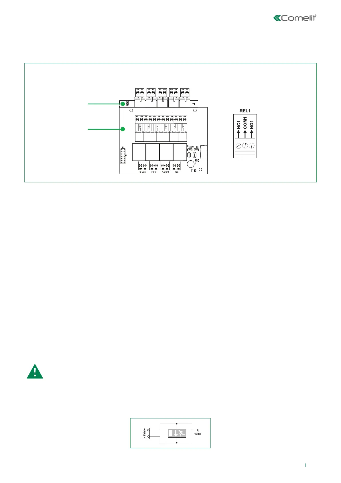
Output module
4 Relay Module
REL 1 REL 2 REL 3 REL 4
24V
GND
SND
FAULT R
FIRE R
FIRE P
+ - - + - + - + - +
EFlt
Loop
Description of the monitored output module terminal block:
• +24 V – Auxiliary output, 24 VDC @ 0.3A
• GND – Auxiliary output common earth
• SND – Monitored output for connection of sounders or visual/audible signalling devices. Enabled if there is an ACTIVE loop
sounders event. 24 VDC / 1A
• FIRE R – Monitored output for the connection of external devices such as equipment for fire alarm transmission to the Fire
Brigade. Comes on in the event of a Common Fire Alarm. 24 VDC / 100 mA
• FIRE P – Monitored output for the connection of external devices such as fire protection and extinguishing equipment.
Comes on in the event of a Common Fire Alarm. 24 VDC / 100 mA
• FAULT R – Monitored output for the connection of external fault indication devices. This output is DISABLED in the event of
a common fault. 24 VDC / 100 mA
Description of the terminal block for the 4 relay output module:
• REL 1, REL 2, REL 3, REL 4 – Relay outputs with switching (N.C. – COM - N.O.) voltage-free contacts, freely programmable
via the fire panel settings. 30 VDC/10A (each)
• PrConf, FltPr, AlConf, Vds - Monitored inputs for indicating the fire protection and extinguishing equipment status.
CAUTION: It is essential to connect a 10 kOhm terminal resistor in parallel to the furthest device from the
panel in the monitored circuit, so that the panel can constantly check whether the circuit is intact. See
examples below.
The FIRE R outputs (Fire Brigade alarm transmission) and FIRE P (extinguishing) are monitored outputs; the first is dedicated
to the connection of equipment providing fire alarm indications to monitoring authorities, while the second is used to send
activation commands to fire protection and extinguishing systems.
N.B.: The FIRE R and FIRE P outputs are enabled in the event of a “Common Fire Alarm”.
Connection example for an indication device, connected to the FIRE output.
3.5 Connecting devices to the output module
Others:
• Loop - Interface connector for loop expansion connection
• EFlt - Jumper for enabling/disabling Earth Fault indication (Jumper closed, Earth Fault indication enabled)
11