3.7 Power supply unit - panel 41CPE118
FUNCTION DESCRIPTION
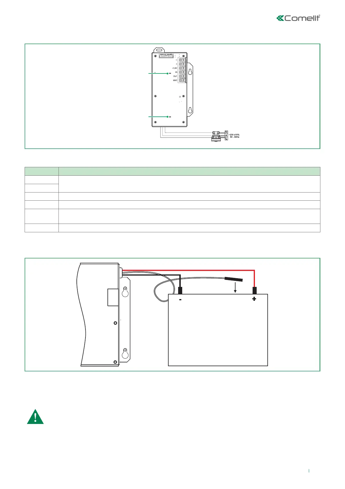
-
Board power supply
+
+13.8 V Additional power supply unit input
IN Input for connection of the additional power supply unit output (Fault Out)
OUT
Error output, enabled when problems arise with the power supply voltage.
It is connected to the additional power supply unit input (Fault In)
GND Input for connecting the additional power supply unit to earth
Description of the power supply unit terminal block
Before connecting the main power supply, make sure each Loop, sounder or other input / output is connected correctly and
the earth cable is connected.
230 V power supply LED
Panel communication LED
4A fuse
Rechargeable sealed
lead battery 12 V / 18 Ah
Main power
supply
Red
Black
Connect the red cable to the positive battery pole, and the black cable to the negative pole.
The two cables should be connected to the battery by means of a Ø5 mm ring terminal.
Position the temperature sensor behind or underneath the battery to ensure the temperature value is read correctly.
CAUTION: When connecting the battery to the power supply unit, several details must be taken into
account.
• Only use batteries which are the correct size with the electrical specifications as indicated by the
manufacturer.
• Before connection to the power supply unit, check the battery polarity.
• The battery cannot power the panel before the mains power is switched on.
• Battery recharging takes place at a maximum current of I = 2A and voltage U ≤ 13.8 V.
15