3. SYSTEM COMPONENTS
3.1 Front panel
Description of LED indications:
• FIRE ALARM: lit steadily in the event of a common fire alarm
• PREALARM: indicates one or more Zones in PreAlarm status
• FAULT: general fault indication (e.g. Device, Device or Panel output, etc.)
• SYSTEM FAULT: indication in the event of a system fault (e.g. Processor)
• SILENCE: general indication for silenced alarms
• DELAY: general indication of a delay for one or more outputs in the system
• AC VOLTAGE: indication that 230 V mains voltage is present
• DISABLEMENTS: indication of active system disablements (e.g. buzzer, device disabled, etc.)
• TEST: lit steadily in Test mode
• WARNING: indication that a technical warning has been received (e.g. input/output of a device enabled)
• ALARM CONFIRMED: indication received from alarm signalling equipment
• OUTPUTS FAULTY/DISABLED: monitored alarm output faulty / disabled
• CONFIRM POWER DOWN: confirmation of the indication received from fire protection equipment
• POWER DOWN FAULT: fault indication received from fire protection equipment
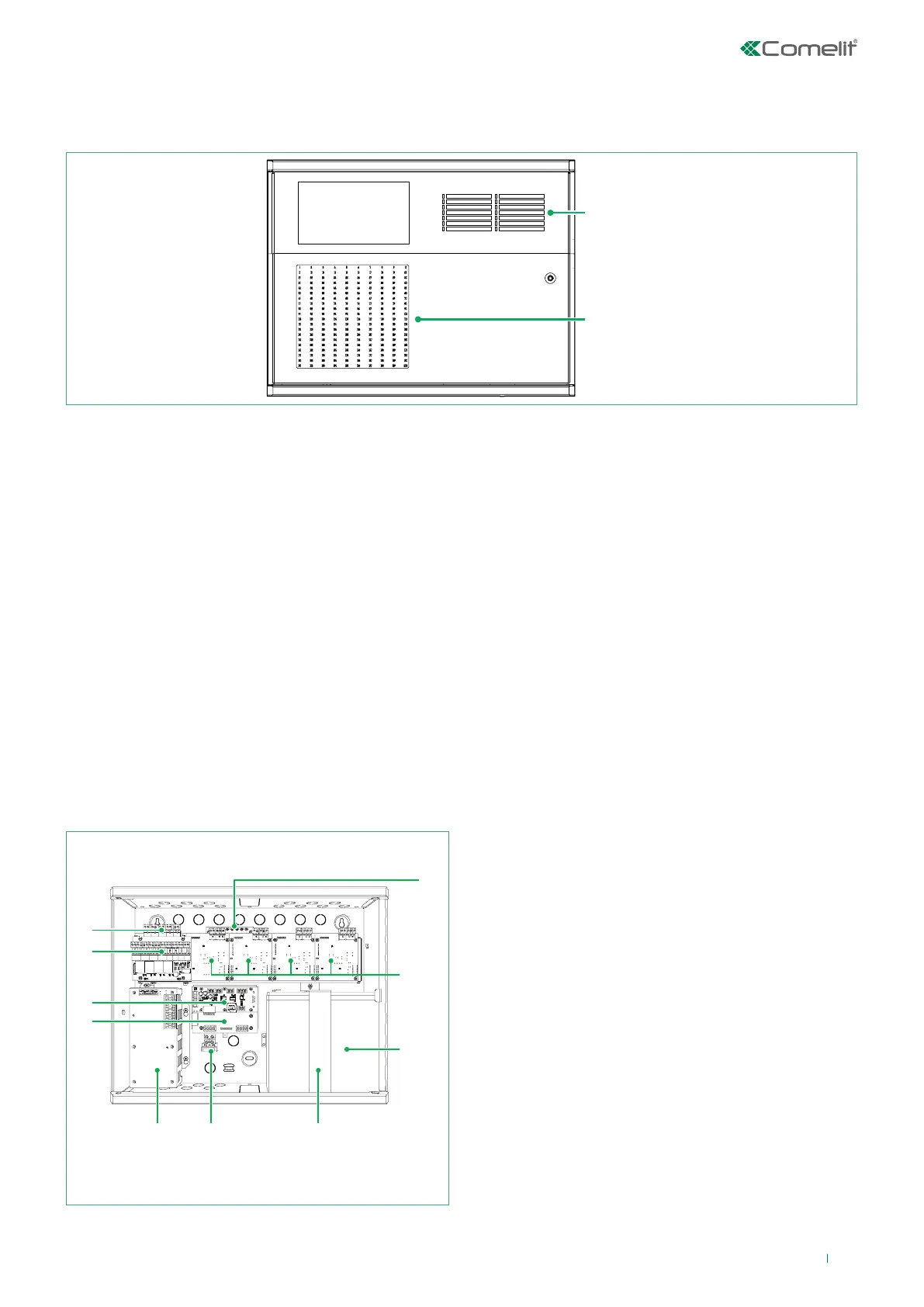
3.2 Internal modules for panel 41CPE118 (full configuration)
1
5
6
7
8
9
10
1. Rechargeable 12 V / 18 Ah battery
2. Battery support bracket
3. Terminal block for connection of the main 230 V power
supply (4A fuse)
4. Main power supply unit
5. 41ECB000 redundant RS485 BUS expansion module
(optional)
6. Module for interfacing with voice evacuation panel (RJ45)
and RS232 port (printer connection or ESPA 4.4.4 protocol
interfacing)
7. Module with 4 relay outputs and voltage-free switching
contacts, plus 4 monitored inputs
8. Module with 4 monitored outputs
9. Loop boards from 1 to 4 (1 by default)
10. Facility for securing earth terminal block
Indicator LED
Zone indication LED
9