41CPE104 technical / electrical specifications
• Loop controller – from 1 to 4 (1 by default)
• Up to 250 devices (modules and/or sensors, regardless of type) for every Loop 41ECL120
• Max. current for each Loop board - 700 mA
• Communication protocol for Loop expansion devices 41ECL120 - Comelit
• Monitored outputs - 1 (SND) for sounder connection = 1A @ 24 VDC
• AUX output (terminals +24 V and GND) - 1 x 24 VDC@0.5A
• Certification according to EN54-2, EN54-4 and complies with EN54-13
• Main power supply - 110-230 VAC
• Frequency - 50/60 Hz
• Battery – 1 x 12 V / 18 Ah, SLA (Sealed lead-acid) type
• Battery connection type: with ring terminal Ø5 mm (M5)
• EFlt - Jumper for enabling/disabling Earth Fault indication (Jumper closed, Earth Fault indication enabled)
• Dimensions (LxHxD) - 430x330x150 mm
• Material – Metal
• Protection rating - IP 30
• Colour - Grey RAL 7045
• Weight – 7 kg
• Operating temperature – from -10 to +50°C
• Relative humidity - up to 95% (without condensation)
• Storage temperature - from -10°C to +60°C
• Designed for mounting in modular structures
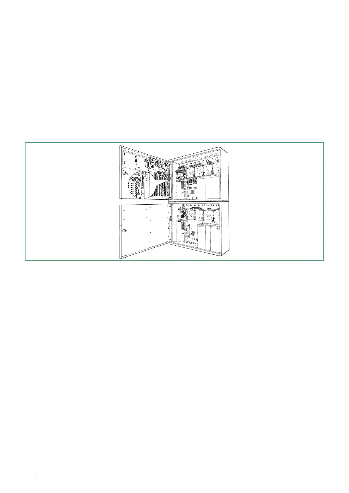
3.6.1 4-Loop expansion box - 41CPE104 (optional)
Expansion box 41CPE104 for panel 41CPE118 is supplied as standard with 1 Loop, which can be expanded to 4 using 3
boards 41ECL120. This means fire panel 41CPE118 can reach its maximum expansion with a total of 8 Loops. Up to 250
addressed devices (detectors, buttons, I/O modules, sounders, etc.) can be connected to each loop. It has a tough grey metal
container which is the same size as the panel and other Comelit modular boxes, to guarantee its modularity and ensure it can
be fitted alongside other boxes during installation.
It has a 14A power supply unit with a 12 V battery output (12 V / 18 Ah).
Certification according to EN54-2, EN54-4 and complies with EN54-13.
Fitting and connecting the communication cable
Combining and fitting modular structures takes place using the screw kit provided.
To connect the communication cable between box 41CPE104 and fire panel 41CPE118, simply connect the flat cable located
inside the additional box to the dedicated terminal inside panel 41CPE118.
14