GE 300 4. Cabling
3.3/0518 15
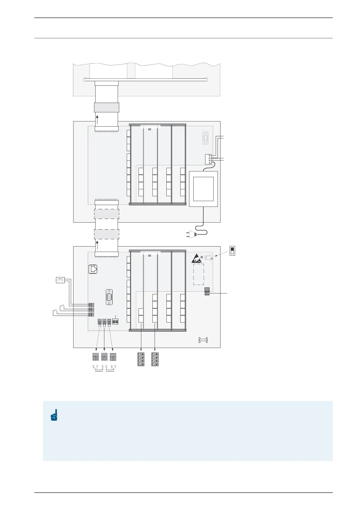
Connection diagram
Overview connection Diagram GE 300, GE 300WR, GEZ 300, GEI 300
ATTENTION: Installation GE 300, GE 300WR and GEZ 300
For DC power supply of the combination of a GE 300 and GEZ 300, one of the components must be
supplied via an additional galvanically isolated DC/DC power supply. This does not apply to the com-
bination of a GE 300WR and GEZ 300, as the GE 300WR comes with a built-in galvanically isolated
DC/DC power supply.
When using the plug-in card G3-8E8A in the GE 300, GE 300WR or GEZ 300, four pins of the main-
board remain unused!
24 VAC
24 VAC
+30V
–
–+
1
6
2
7
3
8
4
9
5
10
GE 300/
GE 300WR
AA
BB
AC
BD
GEI 200
GEZ 300
+
+
-
-
GEI 300
status LED
status LED
connection for
DC power cable
GE 300: 24 VDC (±5%)
ON
OFF
IP
RS-232
IN2
IN1
MUSIC
M3
OUT1
OUT1
OUT2
OUT2
1234
DIP switches
+
+
-
-
power
slot number
expansion jack
expansion jack
input
music/alarm
inputs for
ƃQCVKPI
contacts
slot number
slot 11 slot 12
e.g. G3-GED-4
e.g. G3-16A
e.g. G3-GET-4
30 VDC
supply
optionally
instead of
24 VAC
optionally:
30 VDC
output
max. 100 mA
GEZ 300
(or
GEI 300)
e.g. G3-16A
e.g. G3-GET-4
e.g. G3-GET-4
e.g. G3-GET-4
e.g. G3-GET-4
e.g. G3-GET-4
e.g. G3-GET-4