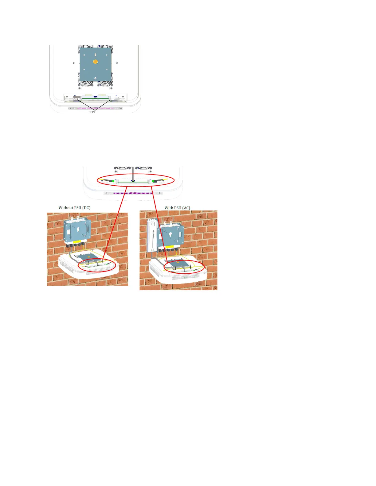
13. Li the UAP2 close to the splice box plate.
a. Connect the cables from the splice box to the UAP2 SFP+ modules. Depending on the conguraon,
there may be one cable (Primary) or two cables (Primary and Secondary).
b. For AC power conguraons only, connect the PSU cable to the connector on the UAP2.
14. Aach the UAP2 to the splice box base plate.
a. Align the keyhole opening on the splice box mounng plate with the buon on the AP mounng
plate.
b. Insert the AP into the splice box mounng plate slot and slide unl the AP plate meets the tabs on
the splice box plate.
15. Push the UAP2 downward and slide it into the locked posion.
16. If using a PSU, plug the AC power cord into an AC power source.
DRAFT: CONFIDENTIAL
Chapter 4: Mount the Fiber UAP2
CommScope ERA
®
UAP2 with Fiber Interface Installaon Guide , Release
P/N M0203AB, DRAFT Rev D 37