This should be on when there is power to the unit.
In normal operation, this should flash slowly, and then flash quickly
when the nozzle switch is lifted.
These LEDs correspond to side A and B motors and solenoids. They
will light up according to the hardware they represent.
See the following table for the output LEDs for each application.
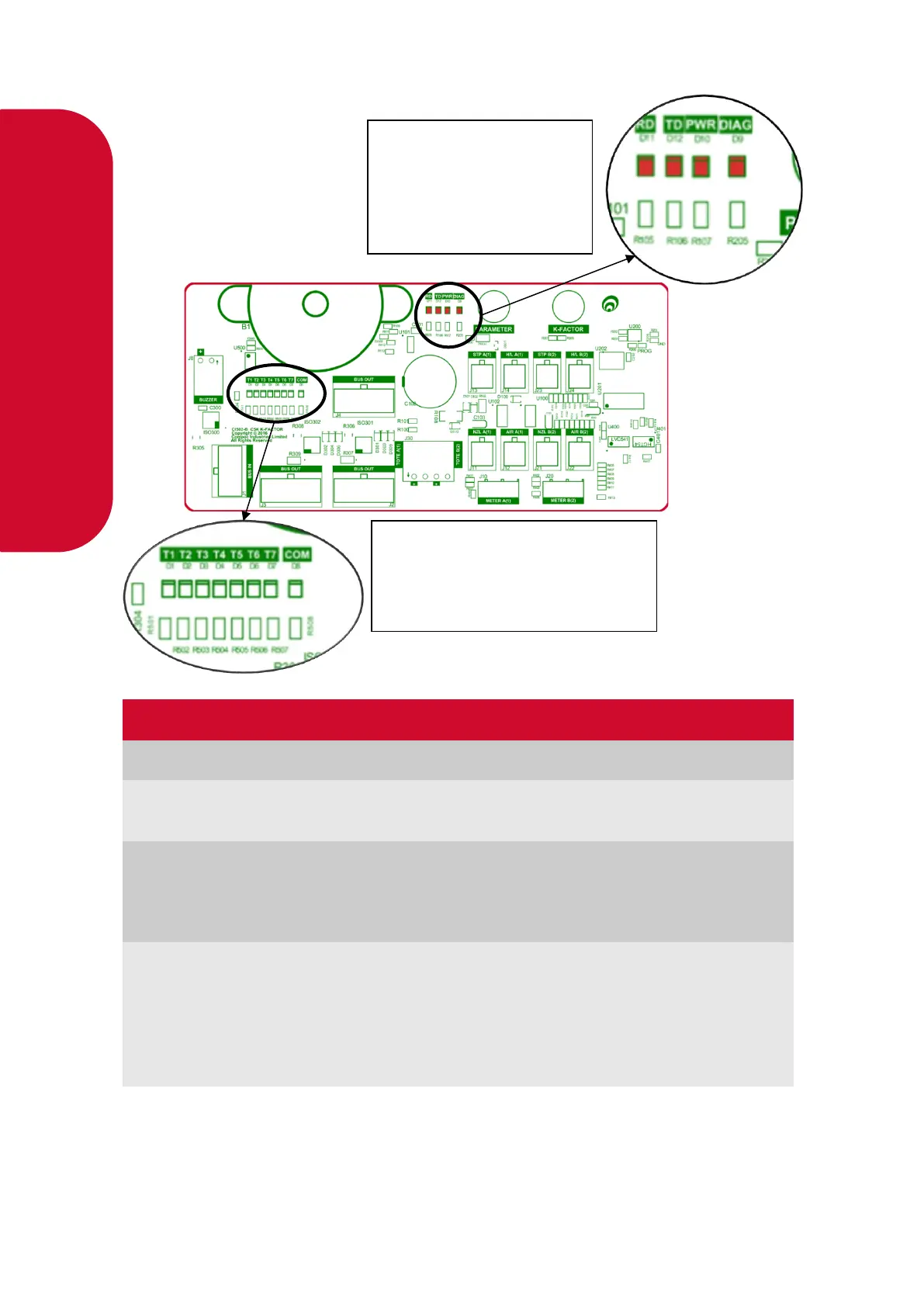
Receiving data/
Transmitting data
In normal operation, these should be on when the Diagnostics light is
on, and off when the diagnostics light is off.
If the diagnostics light is on, and the TD/RD LEDs are off, this means
these is an error. This could be due to cabling – check the bus
system cables.
TD: Transmitting Data
PWR: Power
T1-7: Output LEDs – depend on
application
COM: Not currently in use