. . . . . . . . . . . . . . . . . . . . . . . . . . . . . . . . . . . . .
6-10
Armada MiniStation Removal and Replacement Procedures
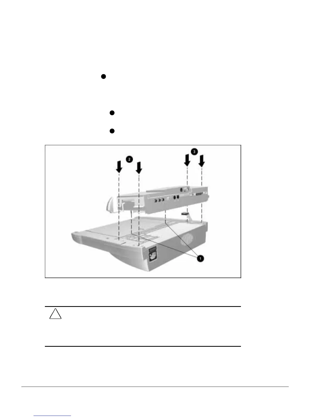
To install the module assembly, follow these steps:
1. Align the alignment pins on the bottom of the module assembly with the holes in
the base assembly
1
and place the module assembly on the base assembly (Figure
6-10).
2. Press firmly on the front of the module assembly to properly seat the module
assembly connector board.
3. Install the two screws
2
on the right side (the side with the docking lever) of the
assembly.
4. Install the two screws
3
on the left side of the assembly.
Figure 6-10.
Installing the Module Assembly
5. Connect the power supply cable.
CAUTION:
Be careful when installing and removing the module assembly on the Armada
MiniStation EX model. The assembly includes a multiple-pin connector that must be
connected to the MultiBay/PC Card assembly. Even, firm pressure must be applied to
connect the module assembly to the MultiBay/PC Card assembly.
Failure to exercise caution when installing the module assembly can result in damage to
the connectors on the docking module and MultiBay/PC Card assemblies.