. . . . . . . . . . . . . . . . . . . . . . . . . . . . . . . . . . . . .
5-2
ArmadaStation Removal and Replacement Procedures
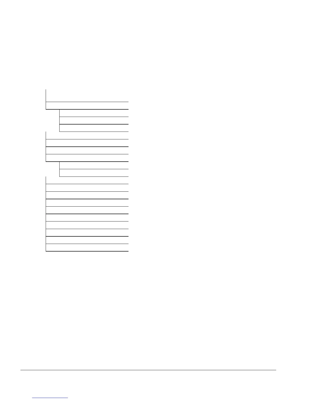
5.2 Disassembly Sequence Chart
Use the chart below to determine the section number and disassembly sequence for
removing components from the ArmadaStation.
5.3 Preparing the ArmadaStation for
Disassembly
5.4 External Components
Compaq Logo
ArmadaStation Feet
Alignment Tray Assembly
5.5 Rear Panel Assembly
5.6 Upper Case Assembly
5.7 Drive Cage Shield
5.8 Half-Height Bays
Half-Height Drives
Half-Height MultiBay Adapters
5.9 I/O Assembly
5.10 Top Brace
5.11 Left Speaker Assembly
5.12 Control Panel Cable
5.13 Control Panel Assembly
5.14 Expansion Boards
5.15 Mechanism Assembly
5.16 Power Supply
5.17 Backplane Assembly
5.18 Expansion Card Cage
Figure 5-2.
ArmadaStation Disassembly Sequence