CONTENTSINTRODUCTION
INSTALLATION
COMMISSIONINGOPERATION
5
Installation
General
The SD3 is designed to connect to an intruder alarm control panel or similar.
The SD3 requires a power input (from an alarm control panel or separate power
supply) of between 10.5V and 28V, with a supply capability of 100mA or greater.
The SD3 is supplied with a 2-metre telephone lead, which plugs directly into any
standard BT socket. Cooper Security recommends that you site the unit as near to
a BT telephone socket as possible. If this it not possible you should either obtain
an approved BT extension lead or permanently wire the unit to the BT socket (see
‘Connections to the telephone line’).
Mounting instructions
1 Separate the cover from the base by using a screwdriver to carefully push two of
the retaining clips (top or bottom) inwards from the base indents.
2 Remove the cover assembly and store in a safe place.
3 Hold the base in position (keyhole to the top) and mark the three securing holes.
Remove the base then drill and plug the holes.
4 Pass all cables into the base through the cable entries and then secure the base to
wall.
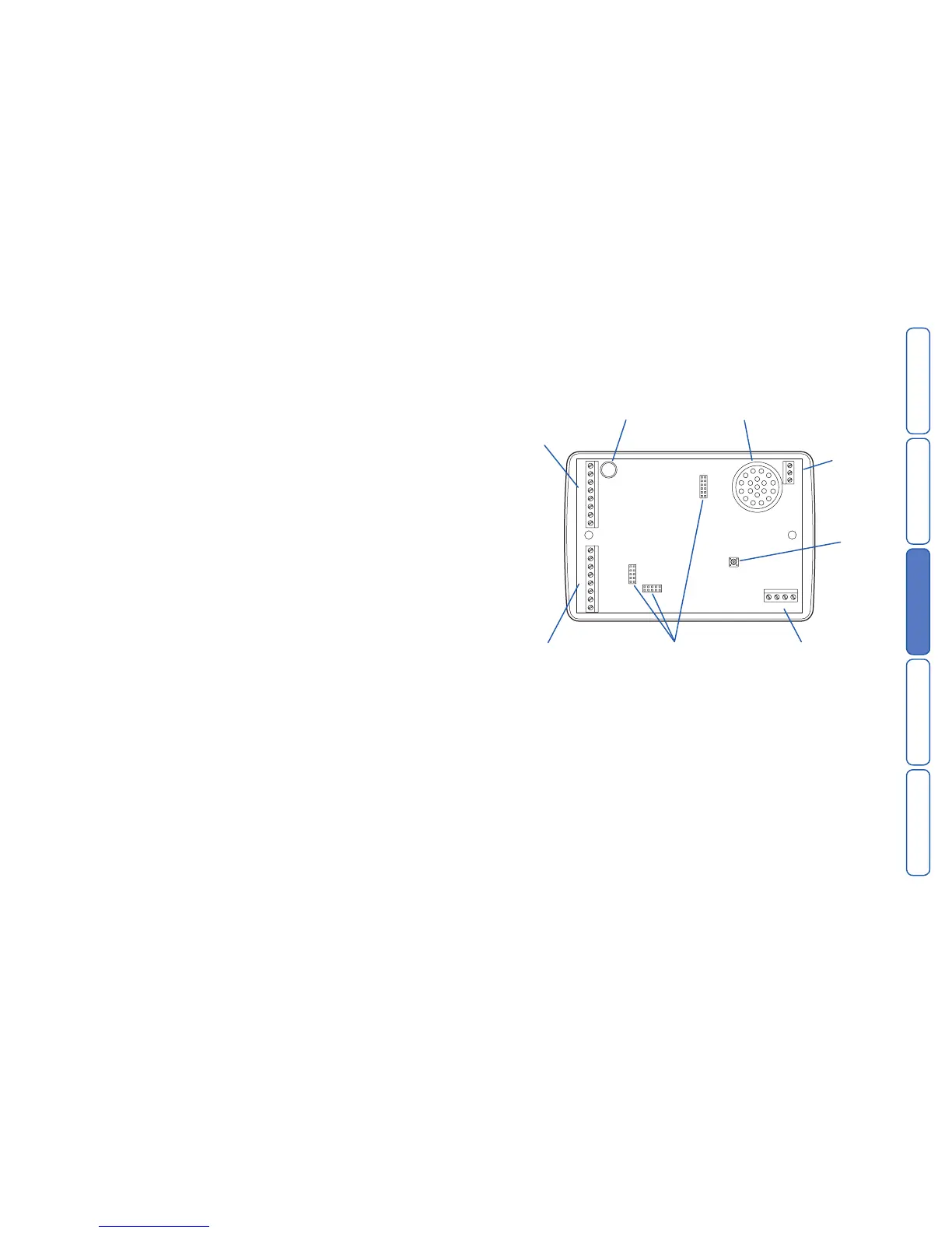
HL
SD3 internal board layout
Connection types and standards
The SD3 connection terminals contain a mixture of alarm system-related connec-
tions and telecommunication connections. The alarm-type connections are termed
Safety Extra Low Voltage or SELV, while the telecommunication connections are
called Telecommunications Network Voltage or TNV.
Note: It is vitally important that the two types of connections are kept separate
and only linked to appropriate external alarm systems and telephone connections,
respectively.
TNV circuits should only be connected by a qualified person in accordance with
local regulations.