IDC Pro 255 Service Manual
© 2016, Cornelius Inc. - 7 - Publication Number: 621058649SER
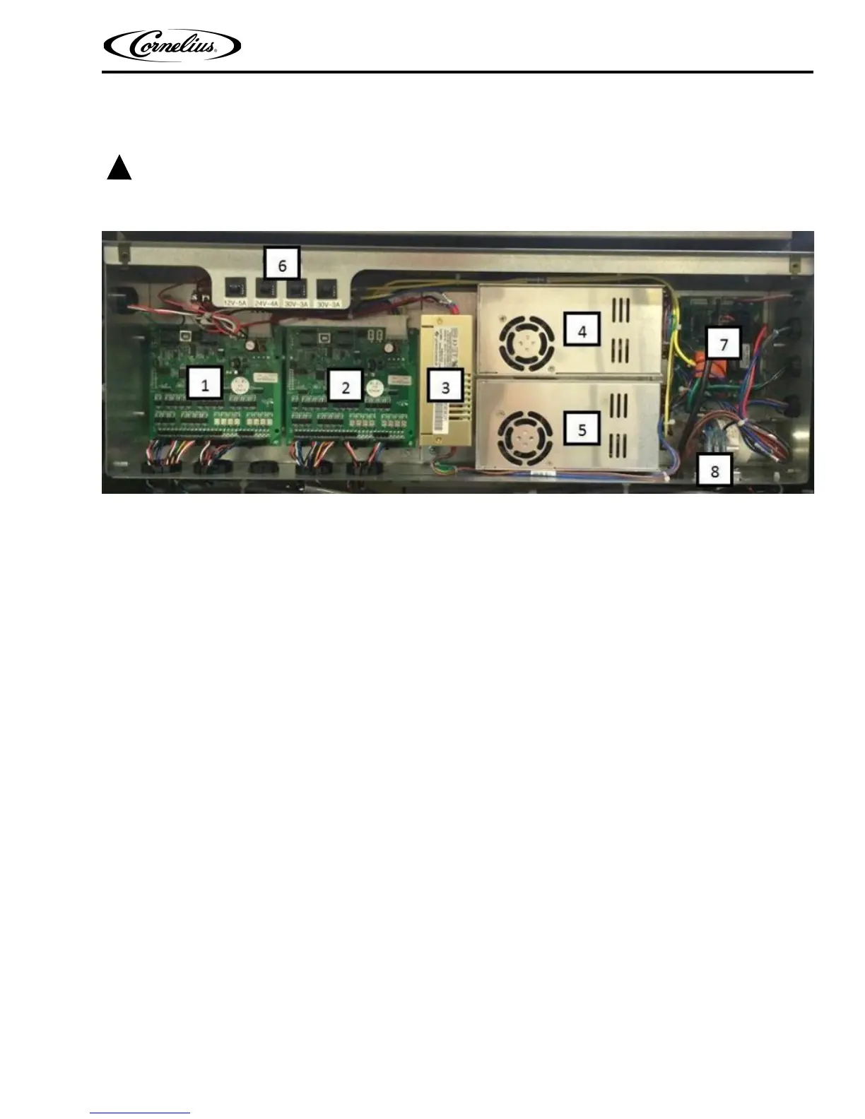
E-BOX CONFIGURATION
Disconnect power to the unit before accessing the E-box.
Figure 3.
1. Left hand valve bank MFV board.
2. Right hand valve bank MFV board.
3. 12VDC/24VDC Power Supply.
A. 12VDV – Control voltage for MFV boards and computer.
B. 24VDC – Powers display and touchscreen.
4. 30VDC Power supply for LH Valve Bank.
5. 30VDC Power supply for RH Valve Bank.
6. Circuit Breakers as follows:
A. 5A – 12VDC
B. 4A – 24VDC
C. 3A – 30VDC
D. 3A – 30VDC
7. Agitation Timer / Liquid Level Control Board.
8. AC Power Inlet.