Prism Owner’s Manual
© 2018, Cornelius Inc. - 11 - Publication Number: 548000096
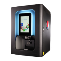
NOTE: Position of the punching may vary, depending upon requirement.
NOTE: With reference to Step - 5, all 2 screws must be tightened to avoid any tool damage or improper
punching.
4. Align the 2 dowel pins of the “Rear
Die”
with Corresponding holes on
the “Valve mounting panel”.
Valve
Mounting
Panel
Rear Die
Figure 15.
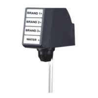
5. Assemble “Front Die” loaded with
“Punch Tool” to “Rear Die”, using 2
Phillip “8-32” screws.
Figure 16.
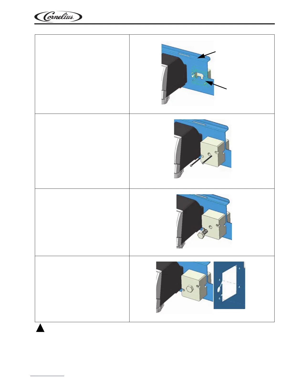
6. Assemble & tighten the hexagon
bolt using socket wrench, until the
bolt head rests on the front die sur-
face.
NOTE: Add lubricant to 3/16” bolt
be
fore using the knockout.
Figure 17.
7. Remove the tool from the valve
mounting panel and dispose of the
punched out piece.
Figure 18.