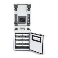
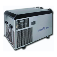
1. Assemble rear cover.
Figure 36.
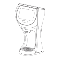
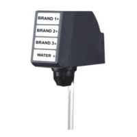
2. Route the wires from valve body and con-
nect with capacitive touch module, refer
Figure 37.
Figure 37.
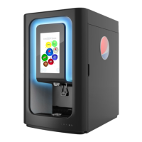
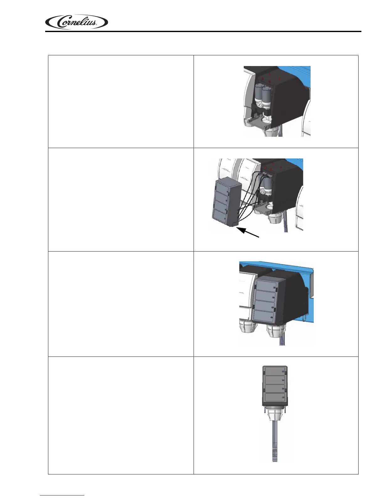
3. Slide the touch module on the rear cover
from top.
Figure 38.
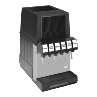
4. Press each button on the capacitive touch
module & visually check the pour.
NOTE: Refer page 6 for ratio information.
Figure 39.
Prism Owner’s Manual
© 2018, Cornelius Inc. - 21 - Publication Number: 548000096
TOUCH MODULE AND COVER INSTALLATION