STANDARD RECOMMENDED PROCEDURE 003-876 | ISSUE 1 | JANUARY 2012 | PAGE 14 OF 21
5.4.
Replace blank panels (Figure 17) with adapter panels
applicable for the connectors being used.
5.5.
Terminate the ber in accordance with company
policies and manufacturer’s recommendations.
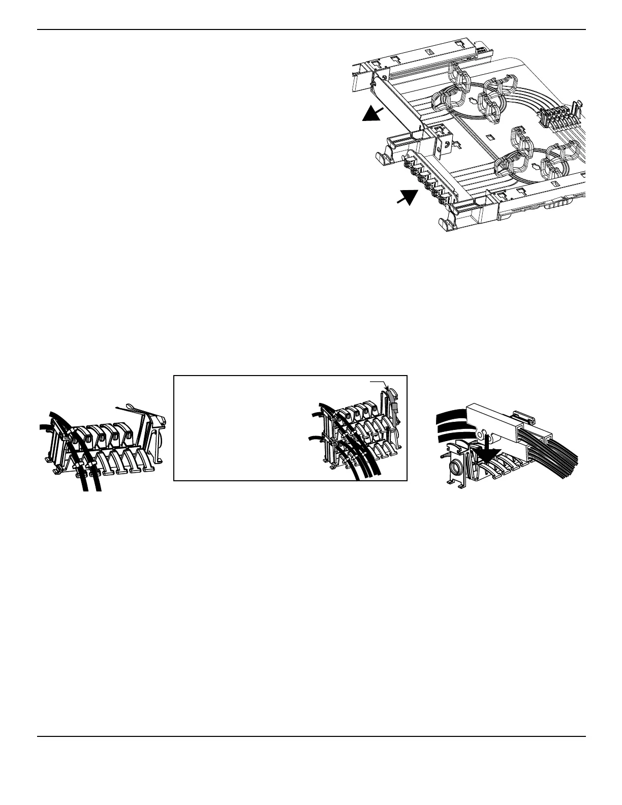
Figure 17
5.6.
The procedure for routing all cable types is the same, unless cable enters the housing through the rear
door. If cable enters from the the rear, route one loop of cable around the perimeter of the housing to
the transitional strain-relief holder as shown in Section 5.3.4. Otherwise, route the 900-micron ber
(buffered or furcated) in accordance with the instructional etchings on the sliding tray.
5.6.1
Figure 18
If cable enters the housing through the rear door, make one loop with the cable around the perimeter of
the housing before securing the cable to the holder.
Strain-relieve the cable jacket or the sub-unit jacket to the transitional strain-relief holder with cable ties
on each side of the holder as seen in Figure 18. The transitional strain-relief holder can hold up to six
different cables or sub-units.
• If the cable enters the housing from the right side (as seen from the rear of the housing), route
the cable so that the jacketed cable is on the left and the 900-micron bers exit on the right
side of the transitional holder.
• If the cable enters the housing from the left side (as seen from the rear of the housing), route
the cable so that the jacketed cable is on the right and the 900-micron bers exit on the left
side of the transitional holder.
TPA-3988
In housings taller than
1U, transitional holders
may be stacked to
accommodate more
fan-out bodies or cables.
Secure holders together
with a cable tie.
Transitional Holder
using cable ties
Transitional Holder
using Buer Tube Fan-out Bodies
TPA-3970
Cable Tie