STANDARD RECOMMENDED PROCEDURE 003-876 | ISSUE 1 | JANUARY 2012 | PAGE 19 OF 21
6.2.
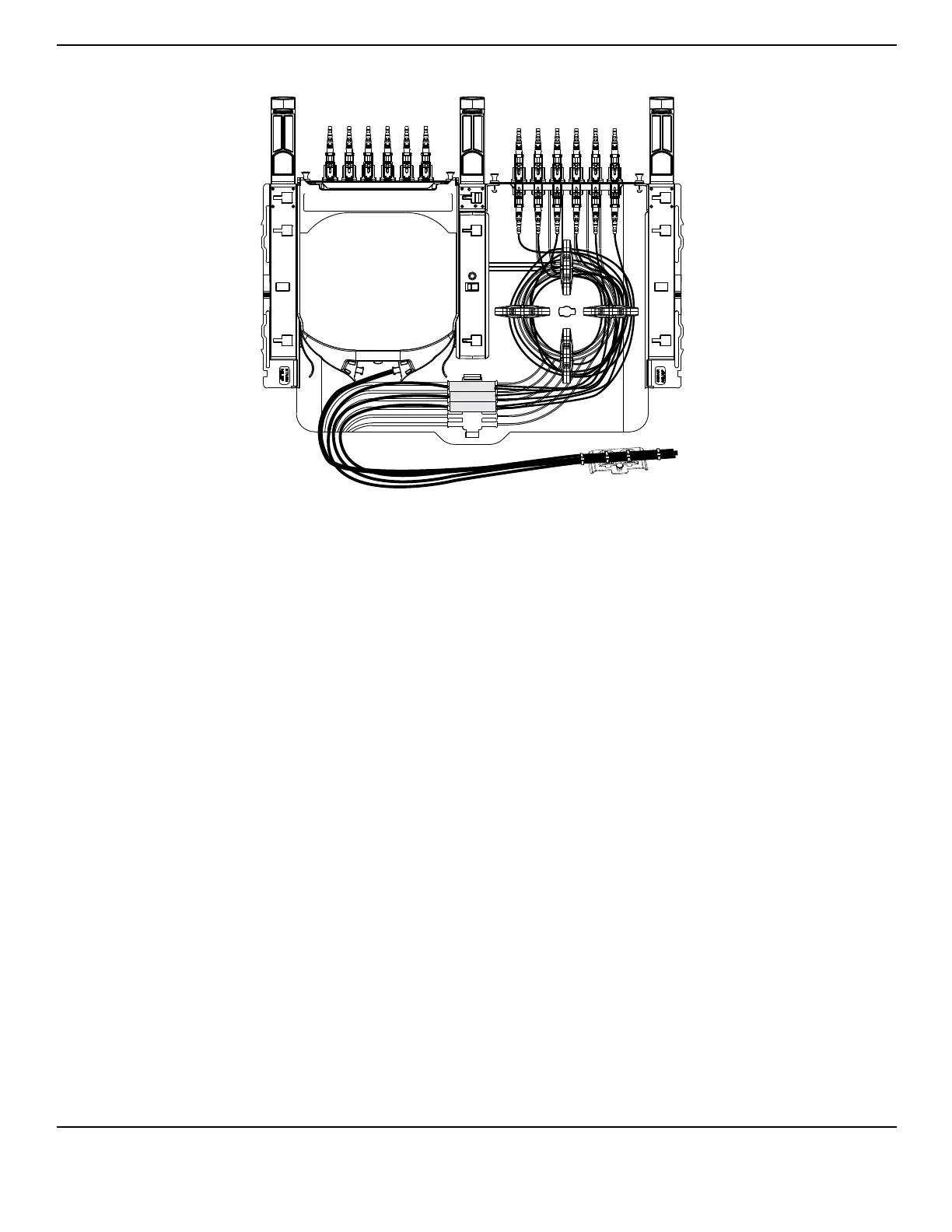
Figure 22
Follow Steps 1 through 3b in Section 6.1.
Remove both blank panels, then remove panel clips on the left side by pulling the clip away
from the panel clip holders and sliding the clips towards the front of the housing.
Insert the rear stacker into the housing by sliding the clips located on the bottom of the
stacker into the slots located in the sliding tray (Figure 21).
NOTE: When installing the stackers into a CCH-02U or CCH-03U housing, the stackers may be mounted
on top of one another using the directions in Step 6.
Install an adapter panel on the right side of the shelf (Figure 22) (as seen from the rear of
the housing).
Assemble external strain-relief assembly depending upon the direction from which cable
enters the housing. Refer to Section 5.3.1 for details.
NOTE: Alternatively, a Universal Cable Clamp may be attached to the strain-relief arm to hold the cable
(Figure 13).
Install the cassette on the left Figure 22), either from the front or rear of the housing between
the stacker and side wall of shelf until it snaps into place. To remove the cassette, press in
on the two tabs and slide the cassette towards either the front or the rear of the housing.
NOTE: Mate the recessed channel along the side of the cassette with the corresponding rails of the shelf
and stacker as you insert the cassette.
Route cables as shown.
NOTE: In CCH-02U (CCH-03U), install up to 2 (3) cassettes on left side of housing and up to 2 (3) panels
on the right side.
TPA-3998