STANDARD RECOMMENDED PROCEDURE 003-876 | ISSUE 1 | JANUARY 2012 | PAGE 15 OF 21
• Strain-relieve the buffer tube by inserting the buffer tube fan-out body into the transitional
strain-relief holder as seen above until it snaps into place.
• If the cable enters the housing from the right side (as seen from the rear of the housing), route
the cable so that the jacketed cable is on the left and the 900-micron bers exit on the right
side of the transitional holder.
• If the cable enters the housing from the left side (as seen from the rear of the housing), route
the cable so that the jacketed cable is on the right and the 900-micron bers exit on the left
side of the transitional holder.
5.6.2
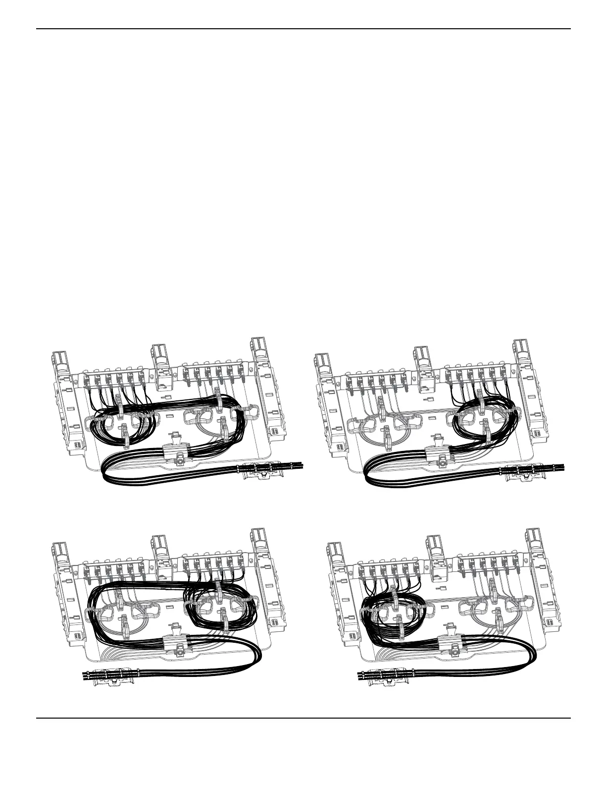
Capture 900-micron ber in the slack management clips as shown and described below.
Route the 900-micron ber inside the slack
management clips for half a rotation. To ensure appropriate ber bend radius, run the ber across
the tray and make a full rotation or more inside the slack management clips on the other side of the
tray. Capture all ber slack inside the clips as shown in Figure 19.
Route the 900-micron ber in a full rotation or more
around the slack management clips, securing all ber slack inside the clips.
Figure 19
TPA-3971
Adapter Panel on Opposite Side from
Right Side Cable Entry
Adapter Panel on Same Side as
Right Side Cable Entry
Adapter Panel on Opposite Side from
Left Side Cable Entry
Adapter Panel on Same Side as
Left Side Cable Entry