STANDARD RECOMMENDED PROCEDURE 003-876 | ISSUE 1 | JANUARY 2012 | PAGE 7 OF 21
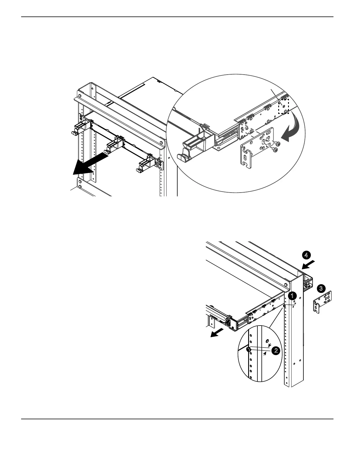
Relocate the bracket to the front of the housing (Figure 5). Align the screws with the
mounting hole locations shown and reinstall the bracket.
Pull the sliding tray out to the detent position so that jumper routing guides project in front of
the rack uprights.
Lock shelf into place, if desired (as shown in inset).
Mount the housing in the rack per the steps in Section 4.1.
Figure 5
4.2.
Identify the rack location where the housing
will be mounted.
Insert the bottom screws into the rack just
above the desired location for the bottom
edge of the housing (#12 screws provided
— one per side), leaving 1/4-inch of screw
threads exposed (Figure 6).
Remove the mounting brackets from the
housing using a Phillips-head screwdriver.
Pass the housing through the rack until the
holes for the mounting brackets are in front
of the rack-mounting rails.
Figure 6
TPA-3977
Insert #6 - 32 x 0.312-inch
screw to lock shelf
Front
TPA-3978
1/4-inch gap
1
3
4
1/4-inch gap
2