STANDARD RECOMMENDED PROCEDURE 003-876 | ISSUE 1 | JANUARY 2012 | PAGE 8 OF 21
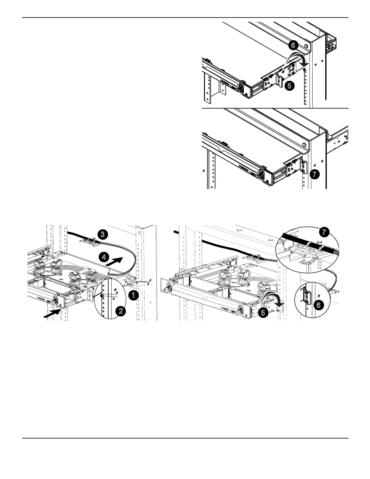
Reattach the mounting brackets using a
Phillips-head screwdriver (Figure 7).
Set the open-ended slot on the bottom of
the mounting brackets onto the installed
screws. (The mounting brackets will
support the weight of the housing.)
Tighten the installed screws and insert
one more screw per side into the center
cut-out of the mounting bracket. (For
CCH-02U and CCH-03U housings: insert
additional screws through the top slot
on the mounting brackets and tighten
securely.)
Figure 7
4.3.
Figure 8
Identify the rack location where the housing will be mounted (Figure 8).
Insert the bottom screws into the rack just above the desired location for the bottom edge of
the housing (#12 screws provided — one per side), leaving 1/4 to 1/2-inch of screw threads
exposed.
Carefully remove the external or internal strain-relief bracket, taking care to protect the cable
or buffer tubes.
NOTE: Slide the covers off to access the internal strain-relief bracket.
Pass the cable and housing through the rack from the front, taking care not to damage the
cable or buffer tubes as you pass the housing through the rack.
5
7
TPA-3979
6
Front
Front
1
3
4
TPA-3980
1/4-inch gap
5
1/4-inch gap
2
7
Front
Front