Do you have a question about the Cosmo DN 25 and is the answer not in the manual?
Describes the manual's purpose and target audience for the mixed pump group.
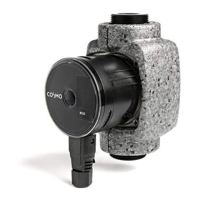
Provides a description of the premounted pump group for heating circuits.
Explains the function of the 3-way mixing valve and its bypass for temperature regulation.
Details how to isolate the pump for maintenance without draining the heating circuit.
Presents a graphical representation of pressure loss versus flow rate.
Warns about proper usage in heating circuits and against use in drinking water applications.
Alerts to damage caused by mineral oils to EPDM seals and provides precautions.
Specifies requirements for the installation location to prevent damage.
Refers to separate instructions for mounting on a distribution manifold.
Details the process for safely removing the pump group from its installation.
Lists available spare parts with their part numbers (KBN) and descriptions.
General advice on installing the controller in a suitable environment.
Illustrates how to mount the controller directly onto the mixing valve.
Describes the physical appearance and components of the controller's interface.
Explains the meaning of the illuminated button for operation mode indication.
Outlines the step-by-step initial setup wizard for the controller.
Details the main LCD display, its layout, and the meaning of its various elements.
Explains the symbols used on the controller's display for different functions.
Covers settings for day and night temperatures for user comfort.
Details special functions like Party, Eco, and Holiday modes.
Explains the different operation modes available for the controller.
Describes how to set and manage time programs for heating.
Allows selection of the user interface language.
Enables setting the current time and date for the controller.
Options to adjust display illumination and auto-exit behavior.
Provides access to temperature history and service data.
Restores all controller parameters to default values.
Saves the current controller configuration as user presets.
Enables loading previously saved user settings.
Allows adjustment of the desired day temperature for heating.
Allows adjustment of the desired night temperature for heating.
Activates comfort temperature operation mode for extended periods.
Activates economic temperature operation mode to save energy.
Activates economy temperature mode for a specified holiday period.
Operates the system based on pre-defined time programs.
Maintains the set day temperature continuously.
Maintains the set night temperature continuously.
Turns off the controller, retaining frost protection.
Selects between heating and cooling modes.
Allows manual control of the mixing valve and circulation pump.
Allows selection from four independent time programs.
Provides tools for copying and editing existing time programs.
Allows selection of the user interface language.
Enables setting the current time and date for the controller.
Shows graphical temperature data for the past week.
Provides detailed graphical temperature data for the current day.
Offers diagnostic data for service personnel.
Lists basic parameters for controller configuration.
Lists service parameters for advanced configuration.
Lists parameters specific to floor drying functions.
Explains how to adjust the heating curve steepness based on system and building characteristics.
Lists parameters related to the floor drying function.
Restores all controller parameters to default values.
Resets all time programs to their default settings.
Saves the current controller configuration as user presets.
Enables loading previously saved user settings.
General advice on installing the controller in a suitable environment.
Illustrates how to mount the controller directly onto the mixing valve.
Explains how to connect the controller to the mains power supply.
Shows the layout of connectors for sensors, room units, and bus connections.
Specifies installation guidelines for the outdoor temperature sensor.
Details the installation and connection of the VL-sensor.
Describes the mounting and connection of a room sensor or unit.
Explains controller behavior when the outdoor sensor fails.
Describes controller response to a failed stand pipe temperature sensor.
Details controller behavior when room sensors are faulty.
Explains controller operation when the return pipe sensor fails.
Describes controller behavior if the boiler temperature sensor fails.
Illustrates the standalone mixing circuit operation.
Lists general specifications like power supply, dimensions, and weight.
Details specific technical parameters such as temperature ranges and controller settings.
Provides information on the proper disposal of electronic waste according to regulations.
| Brand | Cosmo |
|---|---|
| Model | DN 25 |
| Category | Water Pump |
| Language | English |