LEMCOM CANopen® – User manual List of figures
COVAL – LMCOP-EN-A-1155UM0068 49/49
13 LIST OF FIGURES
Figure 1 – Master-secondary island concept ..................................................................................... 8
Figure 2 – Wiring a LEMC--X---W2GB4 island ................................................................................ 10
Figure 3 – Wiring instructions (M8 – CAN bus ports) ....................................................................... 10
Figure 4 – Wiring instructions (M8 – COVAL bus port) .................................................................... 11
Figure 5 – Wiring instructions (M8 – Power port) ............................................................................. 11
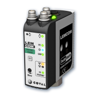
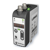
Figure 6 – Front of LEMCOM master Figure 7 – Front of LEMCOM secondary ............... 12
Figure 8 – CANopen NMT state machine (source: CiA) .................................................................. 13
Figure 9 – How the part gripped signal of a LEMCOM module works .............................................. 25
Figure 10 – How the ASC control signal of a LEMCOM module works ............................................ 27
14 LIST OF TABLES
Table 1 – Meaning of indicator lights ............................................................................................... 12
Table 2 – Indicator lights for overall module status .......................................................................... 13
Table 3 – States of the CAN-RUN and CAN-ERR LEDs.................................................................. 13
Table 4 – CAN-RUN indicator light .................................................................................................. 14
Table 5 – CAN-ERR indicator light .................................................................................................. 14
Table 6 – Local bus indicator light (NS) ........................................................................................... 14
Table 7 – Baud rates ....................................................................................................................... 17
Table 8 – Communication objects ................................................................................................... 18
Table 9 – Emergency codes ............................................................................................................ 20
Table 10 – Operating parameters .................................................................................................... 21
Table 11 – Manufacturer-specific objects – Process........................................................................ 22
Table 12 – Manufacturer-specific objects – Diagnosis ..................................................................... 22
Table 13 – Manufacturer-specific objects – Maintenance ................................................................ 22
Table 14 – Manufacturer-specific objects – Parameters .................................................................. 23
Table 15 – Factory settings ............................................................................................................. 39
Table 16 – State of blue customizable LED ..................................................................................... 45
Table 17 – Valve status in case of loss of communication ............................................................... 46