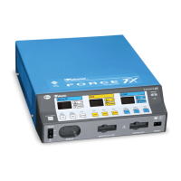
Force FX Electrosurgical Generator C Service Manual xi
Enter the Commands. . . . . . . . . . . . . . . . . . . . . . . . . . . . . . 5-43
Disconnect the Computer from the Generator . . . . . . . . . 5-46
Chapter 6. Troubleshooting
Inspecting the Generator. . . . . . . . . . . . . . . . . . . . . . . . . . . . . . . 6-2
Inspecting the Receptacles . . . . . . . . . . . . . . . . . . . . . . . . . . 6-2
Inspecting the Internal Components . . . . . . . . . . . . . . . . . . 6-3
Correcting Malfunctions . . . . . . . . . . . . . . . . . . . . . . . . . . . . . . . 6-4
Responding to System Alarms . . . . . . . . . . . . . . . . . . . . . . . . . . 6-11
Correcting T_ON ASIC Malfunctions . . . . . . . . . . . . . . . . . . . . . 6-22
Correcting Battery-Backed RAM Malfunctions . . . . . . . . . . . . 6-24
Chapter 7. Replacement Procedures
Interconnect Diagram . . . . . . . . . . . . . . . . . . . . . . . . . . . . . . . . . 7-2
Battery Replacement . . . . . . . . . . . . . . . . . . . . . . . . . . . . . . . . . . 7-3
Control Board Replacement . . . . . . . . . . . . . . . . . . . . . . . . . . . . 7-4
Display Board Replacement. . . . . . . . . . . . . . . . . . . . . . . . . . . . . 7-5
Remove the Display Board . . . . . . . . . . . . . . . . . . . . . . . . . . 7-5
Install the Display Board . . . . . . . . . . . . . . . . . . . . . . . . . . . . 7-6
Display Board Seven-Segment LED Replacement. . . . . . . . . . . . 7-7
Fan Replacement . . . . . . . . . . . . . . . . . . . . . . . . . . . . . . . . . . . . . 7-7
Footswitch Board Replacement. . . . . . . . . . . . . . . . . . . . . . . . . . 7-8
Front Panel Replacement. . . . . . . . . . . . . . . . . . . . . . . . . . . . . . . 7-9
Remove the Front Panel Assembly . . . . . . . . . . . . . . . . . . . . 7-9
Remove and Reinstall the Front Panel Components . . . . . . 7-9
Install the Front Panel Assembly. . . . . . . . . . . . . . . . . . . . . 7-10
Front Panel REM Module Replacement . . . . . . . . . . . . . . . . . . 7-11
Front Panel Power Switch Replacement . . . . . . . . . . . . . . . . . . 7-12
Fuse Replacement . . . . . . . . . . . . . . . . . . . . . . . . . . . . . . . . . . . 7-13
Replacing Fuses in the Fuse Drawer . . . . . . . . . . . . . . . . . . 7-13
Replacing the Fuse on the Power Supply/RF Board. . . . . . 7-14
Left Front Heat Sink and Component Replacement . . . . . . . . 7-15
Remove the Left Front Heat Sink . . . . . . . . . . . . . . . . . . . . 7-15
Replace Left Front Heat Sink Components . . . . . . . . . . . . 7-16
Install the Left Front Heat Sink. . . . . . . . . . . . . . . . . . . . . . 7-16
Left Rear Heat Sink and Component Replacement . . . . . . . . . 7-17
Remove the Left Rear Heat Sink. . . . . . . . . . . . . . . . . . . . . 7-17
Replace Left Rear Heat Sink Components . . . . . . . . . . . . . 7-18
Install the Left Rear Heat Sink . . . . . . . . . . . . . . . . . . . . . . 7-18
Right Heat Sink and Component Replacement . . . . . . . . . . . . 7-19
Remove the Right Heat Sink . . . . . . . . . . . . . . . . . . . . . . . . 7-19