Periodic Safety Check
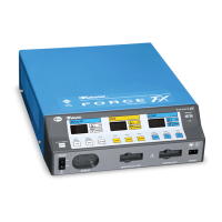
5-16 Force FX Electrosurgical Generator C Service Manual
Inspecting the Generator and Accessories
Equipment required
• Bipolar footswitch or monopolar footswitch
• Bipolar instrument cords (handswitching and footswitching)
• Monopolar instrument cords (handswitching and footswitching)
Turn off the generator, and disconnect the power cord from the wall receptacle.
Rear Panel
1. Check the rear panel footswitch receptacles for obstructions or damage. Check for a
secure fit by inserting the bipolar footswitch or monopolar footswitch connector into
the appropriate receptacle.
2. Remove the fuse and verify correct voltage and current rating. Refer to Performance
Characteristics on page 3-2.
If either connection is loose, replace the Footswitch board assembly. Refer to Footswitch
Board Replacement on page 7-8.
Front Panel
1. Check the Bipolar Instrument receptacle for obstructions or damage. Insert the
bipolar instrument connector (footswitching and handswitching) into the appropriate
receptacle to verify a secure fit.
If the connection is loose, replace the front panel assembly. Refer to Front Panel
Replacement on page 7-9.
2. Check the monopolar instrument receptacles for obstructions or damage. Insert the
monopolar instrument connector (footswitching and handswitching) into the
appropriate receptacle to verify a secure fit.
If any of the connections are loose, replace the front panel assembly. Refer to Front
Panel Replacement on page 7-9.
3. Check the Patient Return Electrode receptacle for a broken pin or an obstruction. If
the receptacle is damaged or obstructed, replace the front panel assembly. Refer to
Front Panel Replacement on page 7-9.
Footswitch
1. Disconnect the footswitch from the generator.
2. Disassemble the footswitch connector. Inspect the connector for damage or corrosion.
3. Reassemble the footswitch connector.
4. Inspect the footswitch for damage.