General Description
1-2 Force FX Electrosurgical Generator C Service Manual
General Description
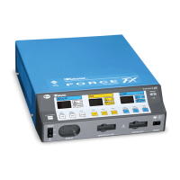
The Covidien Force FX Electrosurgical Generator C is an isolated output electrosurgical
generator that provides the appropriate power for cutting, desiccating, and fulgurating
tissue during bipolar and monopolar surgery.
It includes the following features:
• Instant Response technology
• Three bipolar modes: precise (low), standard (medium), and macro (macrobipolar)
• Three monopolar cut modes: low, pure, and blend
• Three monopolar coag modes: desiccate (low), fulgurate (medium), and spray (high)
• Support for simultaneous coagulation
• The REM
TM
Contact Quality Monitoring System
• Support for ultrasonic electrosurgery using the CUSA EXcel
TM*
system and a CUSA
TM*
handpiece with a CUSA electrosurgical module (CEM
TM*
) nosecone
• Handswitch or footswitch activation
• Recall of most recently used mode and power settings
• Adjustable activation tone volume
• An RF activation port, RS-232 serial port, and expansion port
• Valleylab
TM
Argon Gas Delivery Unit II system compatibility
List of Components
The Force FX Electrosurgical Generator C is a self-contained unit, consisting of a main
enclosure (cover and base) and power cord.
The main components of the generator are the following:
• Front panel components—power switch; controls for setting the modes and output
power; a button for recalling the power settings and modes that were used last;
receptacles for connecting electrosurgical accessories; and indicators that alert you to
the current settings and patient return electrode status.
• Rear panel components—volume control; three footswitch receptacles; power entry
module; equipotential grounding lug; and three ports (serial port, RF activation port,
and expansion port).
• Internal components—Control (microcontroller) board; Display board; Footswitch
board; Power Supply/Radio Frequency (RF) board; low voltage power supply; fan; and
heat sinks.
A handle is located on the underside of the chassis.
For details about the interaction of the main components and circuit board descriptions,
refer to Chapter 4, Principles of Operation.