Low Voltage Power Supply Replacement
Replacement Procedures
Force FX Electrosurgical Generator C Service Manual 7-23
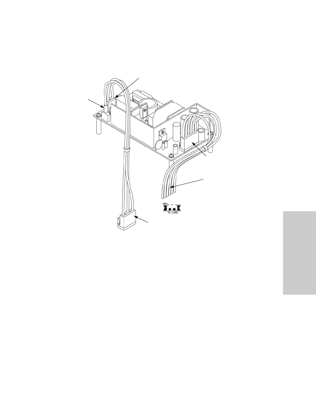
Low voltage power supply
a. Connect the 3-pin cable to J1 at the rear of the low voltage power supply. Verify
that this cable is connected to J7 on the Power Supply/RF board.
b. Connect the red spade lug with the green and yellow ground wire to the ground
lug on the left rear corner of the low voltage power supply.
c. Connect the 6-pin cable to J2 at the front of the low voltage power supply. Solder
the six wires from the opposing end of this cable to the Power Supply/RF board as
follows:
• J2 pin 1 (orange wire) to location BW14 pin 3 on Power Supply/RF board
• J2 pin 2 (red wire) to location BW14 pin 1 on Power Supply/RF board
• J2 pin 3 (red wire) to location BW14 pin 6 on Power Supply/RF board
• J2 pin 4 (black wire) to location BW14 pin 4 on Power Supply/RF board
• J2 pin 5 (black wire) to location BW14 pin 5 on Power Supply/RF board
• J2 pin 6 (blue wire) to location BW14 pin 2 on Power Supply/RF board
Red
Spade
Lug
3-Pin Cable Connected to J1
6-Pin Cable
Connected to
J2
To BW14 on the
Power Supply/RF
Board
To J7 on the Power Supply/RF Board