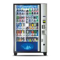
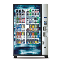
VMC INSTALLATION
Disconnect power to the Vender when replacing the VMC. Once all connectors are positioned on the new
VMC apply power to the Vender. To Set Model Number. On power up the Display will show “Reset Model?
Continue? = Yes CLR = No”. Press the “” Key and Display will show “No Model Set Save? A = ^ (scroll up)
= Yes CLR = No”. Press Key A to scroll through available model numbers 5800-4, 3800-4, 5800-E4 (export),
3800-E4 (export). With Vender model displayed that you are installing the VMC Board press the “” Key to
save. Important: The VMC is sensitive to Electrostatic Discharge (ESD). Failure to handle the VMC carefully
could cause damage, which may result in a Vender being put Out of Service.
ALWAYS GROUND YOURSELF ON THE VENDER CABINET BEFORE INSTALLING OR REMOVING THE VMC
FROM THE MACHINE. ALWAYS TURN POWER OFF BEFORE REMOVING, TOUCHING OR INSTALLING A VMC.
VMC SOFTWARE UPDATE PROCEDURE
The VMC is flash programmable. Note: Updating the VMC is done with a USB Flash Drive. There is no menu
to update the VMC Board software. The following information describes how to update the VMC software.
All new software revisions to the 5 Cabinet Peripheral Control Boards (AC Distribution Box Environmental
Board, X Motor Board, Y Motor Board, Port Board, & Cup Motor Board) will automatically update via the VMC.
Important: USB’s containing software are sensitive to Electrostatic Discharge (ESD). Failure to handle the USB
carefully could cause damage, which may result in a Vender being put Out of Service.
ALWAYS GROUND YOURSELF ON THE VENDER CABINET BEFORE INSTALLING OR REMOVING THE USB FROM
THE VMC. A USB CAN BE USED TO PROGRAM MANY VENDERS. ALWAYS TURN POWER OFF BEFORE
INSTALLING USB IN THE VMC. Important Notes: If needed, use the Programming Guide to program the
Vender.
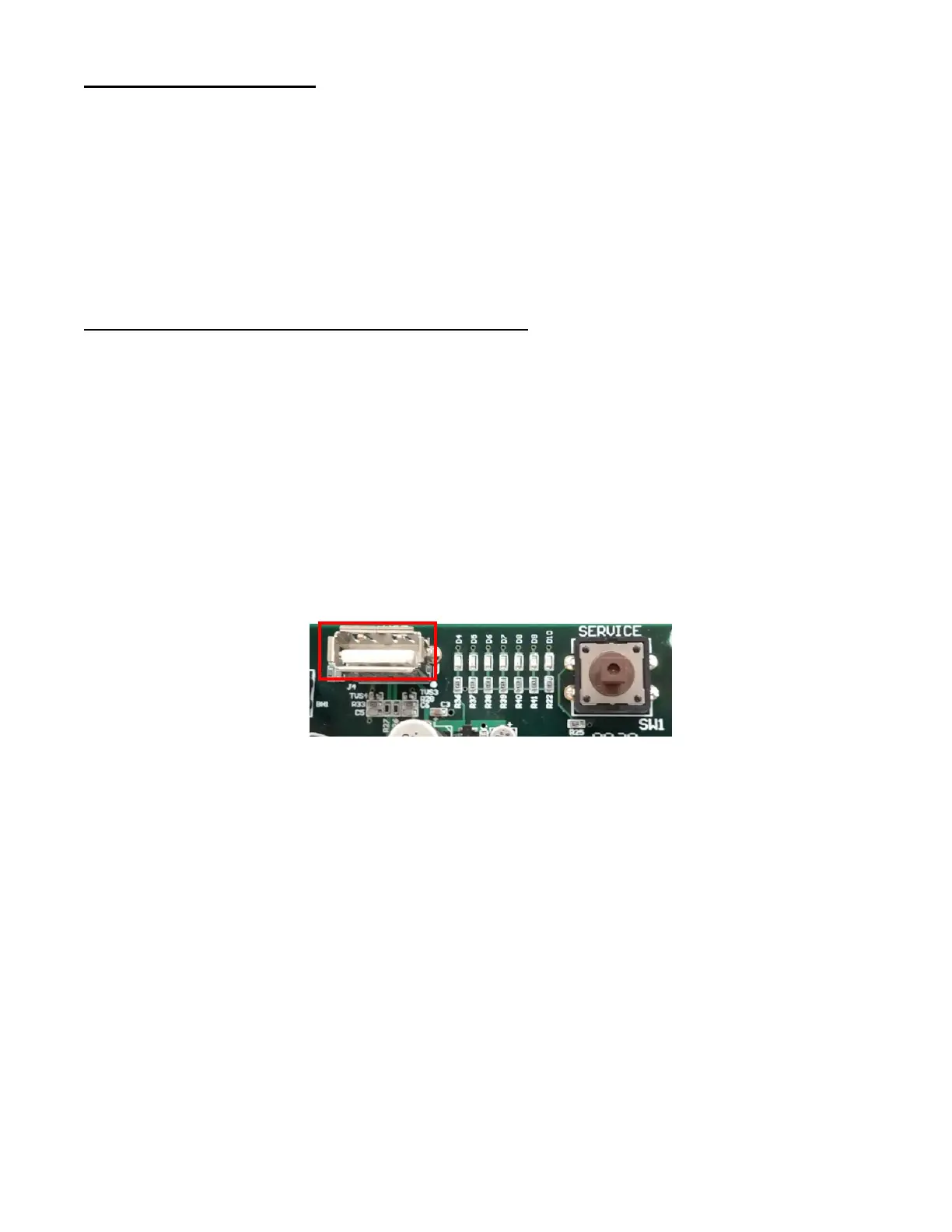
The VMC includes 7 Diagnostics Lights providing information on operational status and where to focus
problem solving efforts.
1. USB Software Installation:
a. Power down the Vender. Ground yourself on the Vender Cabinet.
b. Install the USB in the VMC USB Port.
c. Press and hold the VMC Service Switch (SW1). While holding the Service Switch turn the power
on to Vender.
d. Once the Machine powers on, release the VMC Service Switch (SW1).
e. During software updating the VMC 7 Diagnostic lights (D4 to D10) will flash on and off for
approximately 15 seconds.
f. Once install is complete all 7 VMC Diagnostic lights will be flashing on and off.
g. Remove the USB Flash Drive from the VMC. Note: power does not need to be off to remove the
USB.
h. If only D4 and D10 Diagnostic lights are on at this time, the install was not completed. Repeat
steps “a” through “h”.