BEVMAX REFRESH 4 TROUBLESHOOTING
TROUBLESHOOTING DIAGNOSTIC LIGHTS
With the New Electronics Platform BevMax Refresh 4, troubleshooting is simpler, but it is important to know
how to follow the clues the Vending Machine is presenting. Utilizing error codes while focusing on the Cabinet
Peripheral Control Boards controlling each motor or main component will lead you to a conclusion quickly.
The inner workings of the New Electronics Platform BevMax Refresh 4 is greatly simplified. The AC Distribution
Box sends AC Voltage through an Environmental Board contained within the AC Distribution Box to the
Refrigeration Unit, Evaporator Fan Motor, and the Omron Power Supply.
In turn, the Power Supply returns 24VDC to the Environmental Board within the AC Distribution Box, which
sends both 24VDC and 5VDC to the Vending Machine Controller (VMC). The VMC then sends 5VDC to the X, Y,
Cup, and Port Boards and 24VDC to the MDB components. The Cabinet Peripheral Control Boards run on 5VDC
while allowing 24VDC to pass through to power the Motor Boards or main component each controls.
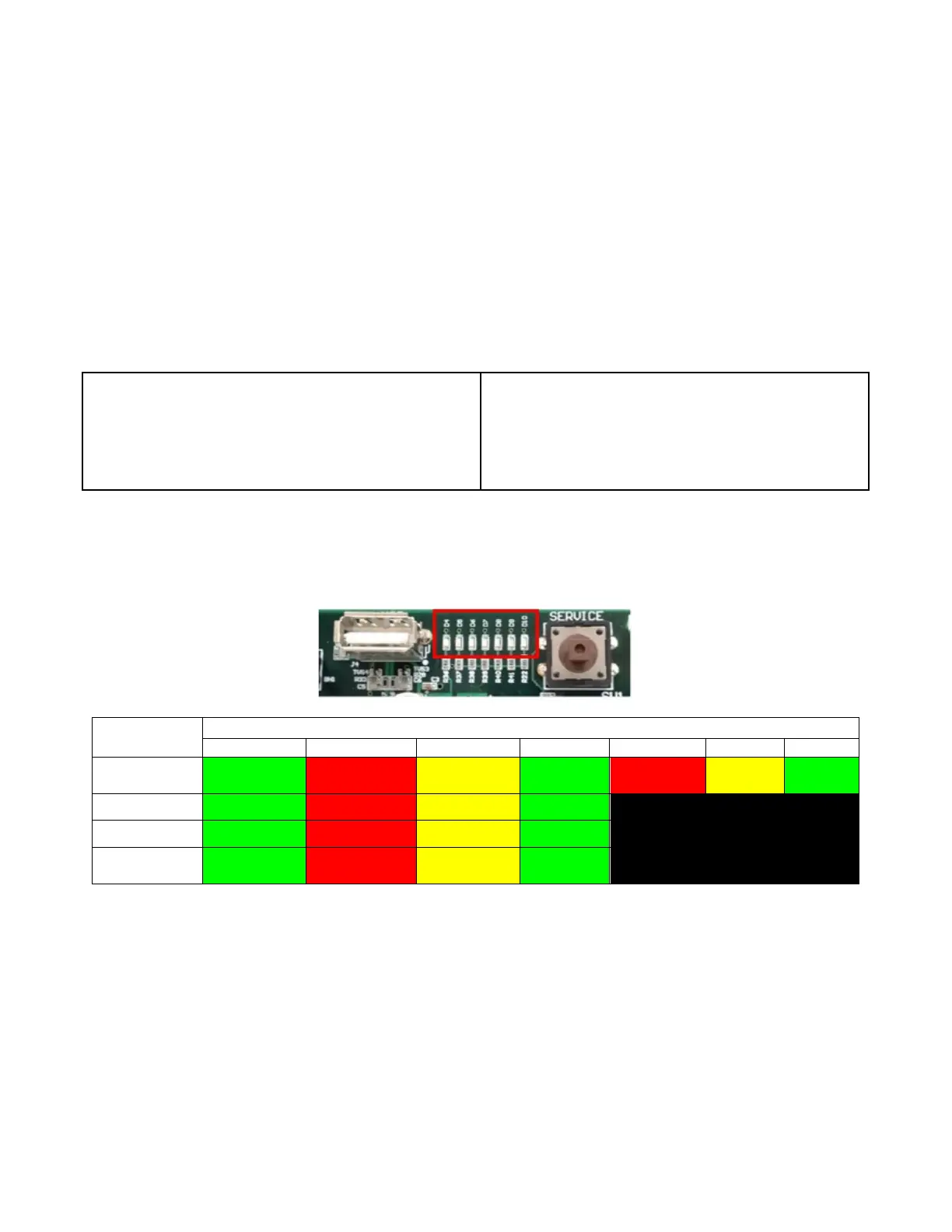
There are 7 Diagnostic Lights across the top of the VMC. These inform the technician of the state of
components when in Normal Mode, Port Test Mode, Cup Test Mode, and Position Test Mode. Use the key to
decipher the meaning of the lights to point you in the right direction quickly.
VMC Diagnostic Lights
Mode
VMC Diagnostic Indicator Lights
USB Power Heartbeat MDB *Keypad
X Home Y Home
Position Test USB Power Picker Home X Home Y Home
Cup Test USB Power Picker Home Cup Sensor Picker Out
Port Test USB Power Port Sensor Port Open
* Green light is off until a key on the Keypad is pressed.
RS 485 Communication Harness A – White wire
RS 485 Communication Harness B – Blue wire
24VDC Motor Power Harness – Red/Green wire
5VDC Harness – Yellow & Red/Yellow wires
Ground Harness – Black wire
24VDC Harness – Red, Red/Blue, & Red/Black wires
24VDC Switched to Vertical Lights = Red/White wire
X Home Switch = Orange wire
3.3VDC Encapsulated Temp. Sensor = Violet wire