Snack - Based Troubleshooting and Repair Guide
September, 2002 Page 11 of 54 1670065
3. As with the selection system, the displays are strobed. Each digit is turned on and off 60
times each second. This fast strobing allows the display to be turned on one digit at a
time, but at a rate so fast that the display is seen as showing complete words and numbers.
The strobed signals to the digit grids are the same signals sent to the column lines of the
selection system, further reducing the number of control lines needed by the microcom-
puter system.
4. The connector configuration for the display board is as follows:
a. J46; J49 Customer and Service Keypad Ports. J46 pins 1-8, and J49 pins 1-4 tap
the strobe signal provided to each digit of the florescent tube when a button is pressed
on one of the keypads. A low is provided by the shift register chip U3, which then
sends the data from the selection button to connector J45 and on to the main controller
board for processing.
b. J47 Is used for FreeVend key switch.
c. J48 Door Switch Port. Door status data is provided at this port. Data is provided to
the shift register chip U3 and sent to the main controller board for processing.
E. Selection Matrix
Most microcomputer systems use a concept known as the Matrix to control (or be controlled by)
various peripheral devises. Keypads, displays, and even the tray system in the snack merchandis-
ers as well as applications for other merchandisers, are all examples of matrixed devises.
Basically, a matrix can be pictured as a grid with vertical and horizontal lines that intersect in a
symmetrical pattern. The points where the lines cross represent an input (switches) or an output
(motor, digit in a display, etc.) to the microcomputer.
The advantage of a matrix system is the ability for the microcomputer to use a large number of
devices with a relatively small number of control lines. For instance the snack merchandisers can
operate as many as 80 different motors with only 21 control lines.
Think of a matrix as a chart or table. A number of rows and columns are used. To find what we
want, we select one row and one column. Where these two lines meet we-find the desired result.
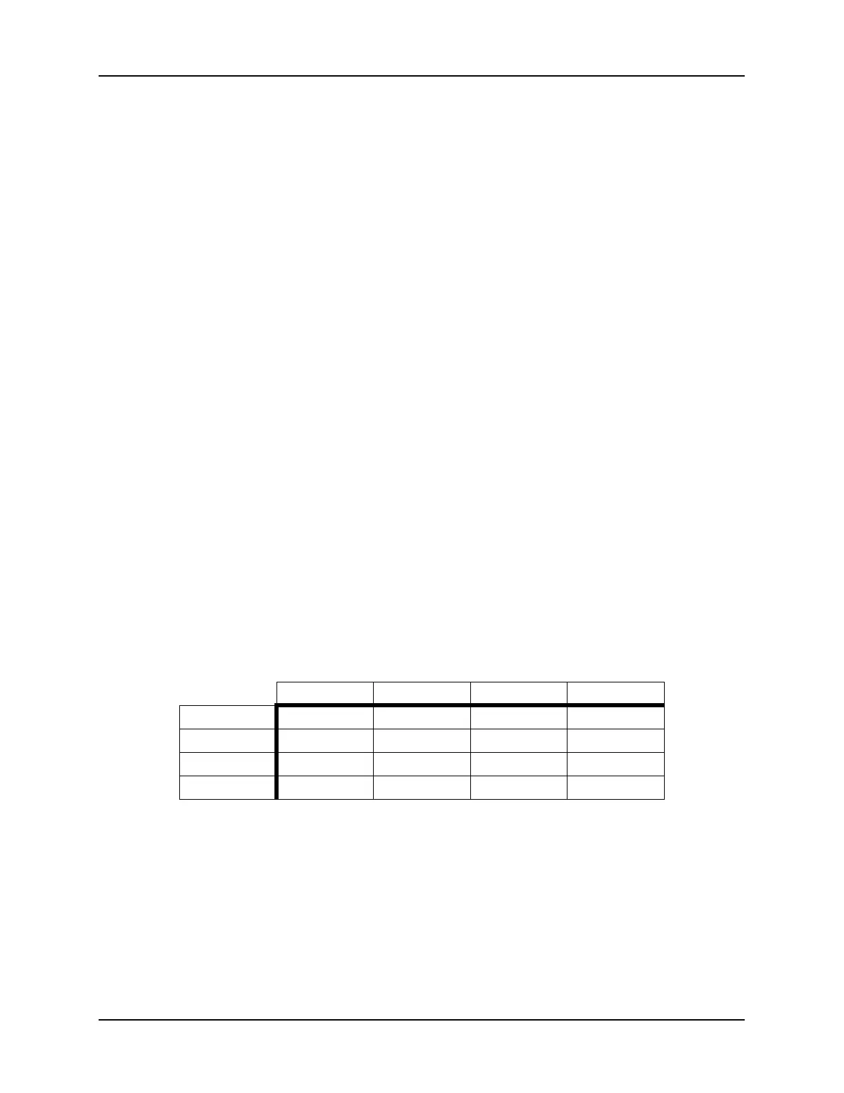
In this example, a 4 x 4 matrix is used (four rows by four columns). If we select Column 3 and
Row 2 and follow them until they intersect, the result is “BROWN”. Notice that we have 16 col-
ors, but only 8 lines (4 rows arid 4 columns). By using the same principle, the microcomputer can
use two signals (one Row and one Column) to turn on a display, operate a motor, or read a switch.
All merchandisers use a switch matrix to determine selections. The standard selection panel is
made up of 21 buttons controlled by 10 lines (7 columns and 3 rows).
Column 1 Column 2 Column 3 Column 4
Row 1 Gray Violet Tan Aqua
Row 2 Yellow Red Brown Black
Row 3 Blue Green Orange Purple
Row 4 White Pink Gold Silver