Snack - Based Troubleshooting and Repair Guide
1670065 Page 4 of 54 September, 2002
Section II. Theory of Operation
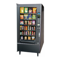
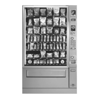
1. Overall Merchandiser
A. Power Circuit
1. The power circuit for the basic snack merchandiser consists of the following components:
Power Cord
Electronic Breaker
Main Switch
Coin Power Board (Optional)
EMI Filter
Main Circuit Breaker
Transformer
2. Power Parameters
a. The merchandiser is supplied with a service cord for the country of use and is termi-
nated in a grounding type plug. The wall receptacle used for this merchandiser must be
properly polarized, grounded, and of the correct voltage. Operating the merchandiser
from a source of low voltage will VOID THE WARRANTY.
b. Each merchandiser should have its own electrical circuit and that circuit should be
protected with a circuit breaker or fuse conforming to local regulations.
3. Power Checks
a. Voltage, polarity, and noise potential checks should be made to determine that each is
of correct level.
b. Voltage (checked between hot and neutral lines), polarity (checked between hot and
ground lines), should indicate 110 - 130 volts ac for 120 volt, 60 Hz locations, or 220
240 volts ac for 230 volt, 50 Hz locations. A noise potential check may be accom-
plished by measuring between neutral and ground. The meter should indicate 0 volts
ac. A measurement greater than 1 - 1.5 volts ac could result in problems for the mer-
chandiser’s electronic circuitry caused by the electrical noise.
4. Main Switch
a. The first component encountered in the power circuit is the main switch. The main
switch is a double pole, single throw switch, rated at 20 amps, ¼ hp, and 125 - 250
volt ac. When the switch is closed or in the “on” position, voltage is transferred to the
EMI filter and throughout the rest of the merchandiser.
 Loading...
