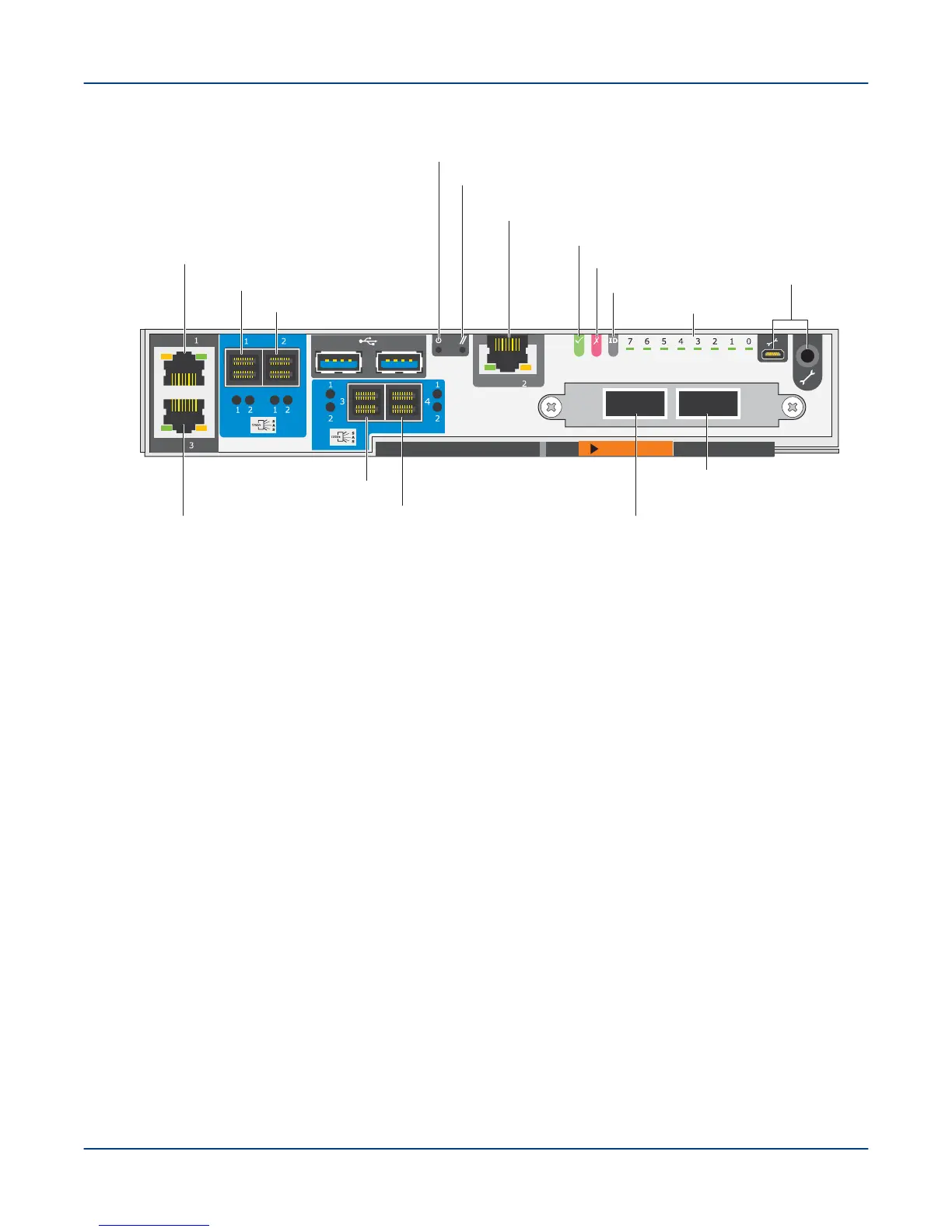
Figure 50. EAC for SSU and MMU
Ethernet NIC 3
eth2 (not used)
SAS port 1
SAS port 2
SAS port 3
SAS port 4
Reset
Power
OK LED
Ethernet NIC 2
mgmt0 (secondary management network)
Fault LED
Diagnostic LEDs
Data network
port I
Data network
port II
Maint ports
ID LED
Ethernet NIC 1
mgmt1 (primary management network)
b. Wait 30 seconds for the drives to spin up.
If power-up is successful, bright LEDs adjacent to the Ethernet ports on each MGMT/MGS/MDS node blink
and turn steady green.
TIP: The MGMT nodes attempt (and fail) to PXE boot before booting from the internal disk. To speed
up the process, especially via a console connection, cancel the PXE boot attempts, which then skip to
booting from the internal disk. If another PXE server is present in the subnet, cancel the PXE boot by
pressing the ESC key or CTRL-C.
The primary and secondary MGMT nodes and the combined MGS/MDS nodes are disk-based and
boot from the internal hard drives, not a PXE server. All OSS nodes are diskless, so they PXE boot
from the secondary MGMT node.
This should power on both MGMT nodes and the combined MGS/MDS nodes.
9. Enable power to the 5U84 SSU controllers.
a. Place the recessed power switches on the PSU in the ON position.
b. Wait 30 seconds for the drives to spin up.
10. If the local management network (LMN) switches are not already powered on, insert their power cords into a
power outlet.
11. For first-time power-on only: Set the static IP address for the management nodes.
Power On the ClusterStor L300 and L300N System
59