EasyManua.ls Logo

Cray CRAY-1 - Page 21

Default Icon
216 pages
Print Icon
To Next Page IconTo Next Page
To Previous Page IconTo Previous Page
Loading...
I
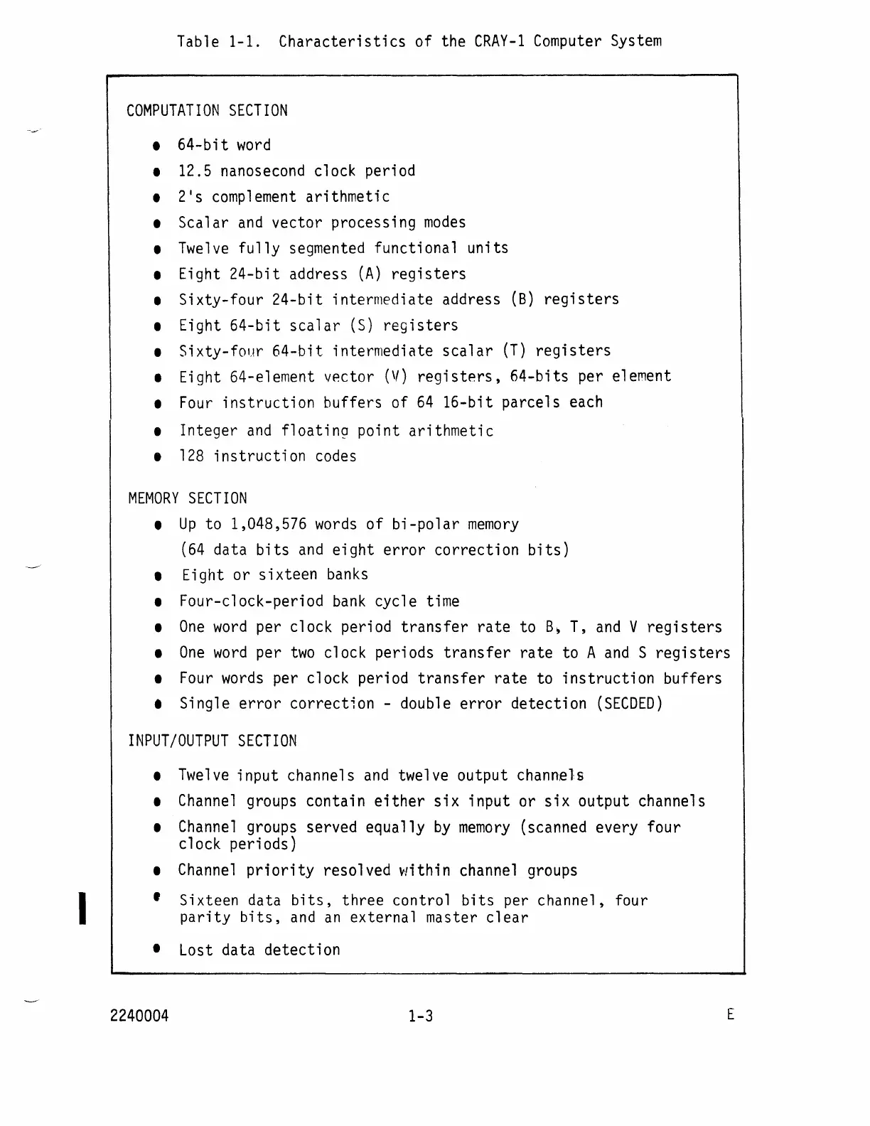
Table 1-1.
Characteristics
of
the
CRAY-l
Computer
System
COMPUTATION
SECTION
•
64-bit
word
• 12.5 nanosecond clock period
• 2
1
s
complement
arithmetic
• Scalar
and
vector processing
modes
•
Twelve
fully
segmented functional units
• Eight
24-bit
address
(A)
registers
• Sixty-four
24-bit
intermediate address (8)
registers
• Eight
64-bit
scalar
(S)
registers
• Sixty-four
64-bit
intermediate
scalar
(T)
registers
• Eight 64-element vector
(V)
registers,
64-bits per element
•
Four
instruction
buffers of
64
16-bit
parcels each
• Integer
and
floating
point arithmetic
•
128
instruction
codes
MEMORY
SECTION
•
Up
to 1,048,576
words
of
bi-polar
memory
(64
data
bits
and
eight
error
correction
bits)
• Eight or sixteen
banks
• Four-clock-period
bank
cycle time
•
One
word
per clock period
transfer
rate
to
B~
T,
and
V
registers
•
One
word
per
two
clock periods
transfer
rate
to A
and
S
registers
•
Four
words
per clock period
transfer
rate
to
instruction
buffers
• Single
error
correction - double
error
detection
(SECDED)
INPUT/OUTPUT
SECTION
•
Twelve
input channels
and
twelve output channels
•
Channel
groups contain
either
six
input or
six
output channels
•
Channel
groups served equally
by
memory
(scanned every four
clock periods)
•
Channel
pri
ori
ty resolved
v-Ji
thi
n channel groups
I Sixteen data
bits,
three control
bits
per channel, four
parity
bits,
and
an
external master
clear
• Lost data detection
2240004
1-3
E

Table of Contents