I
BASIC
CHANNEL
OPERATION
Each
input or each output channel
directly
accesses the
CRAY-1
memory.
Input channels
store
external data in
memory
and
output channels read
data
from
memory.
A primary task of a channel
is
to convert
64-bit
memory
words
into
16-bit
parcels or
16-bit
parcels
,into
64-bit
memory
words.
Four
parcels
make
up
one
memory
word, with
bits
of the parcels assigned to
memory
bit
positions as
shown
in
table
6-1.
In
both input
and
output
operations,
parcel 0
is
always
transferred
first.
Each
channel
consists
of
a data channel
(4
parity
bits,
16
data
bits,
and
3 control
lines),
a
64-bit
assembly or disassembly
register,
a current
address
register,
and
a
limit
address
register.
The
three control
signals
are: ready, resume,
and
disconnect.
These
control
signals
coordinate the
transfer
of parcels over the channels.
The
method
of coordination
varies
among
the types of channel; the
dif-
ferent
methods
are explained
later.
In
addition to the three control
signals,
some
channels
have
a master
clear
line.
The
OJ,
OU,
and
OV
module
input channels (asynchronous)
have
master
clear
lines.
The
DO
module
output channel (high-speed asynchronous)
has
a
master
clear
line.
The
SI
module
output channel (synchronous)
has
a
mas-
ter
clear
line.
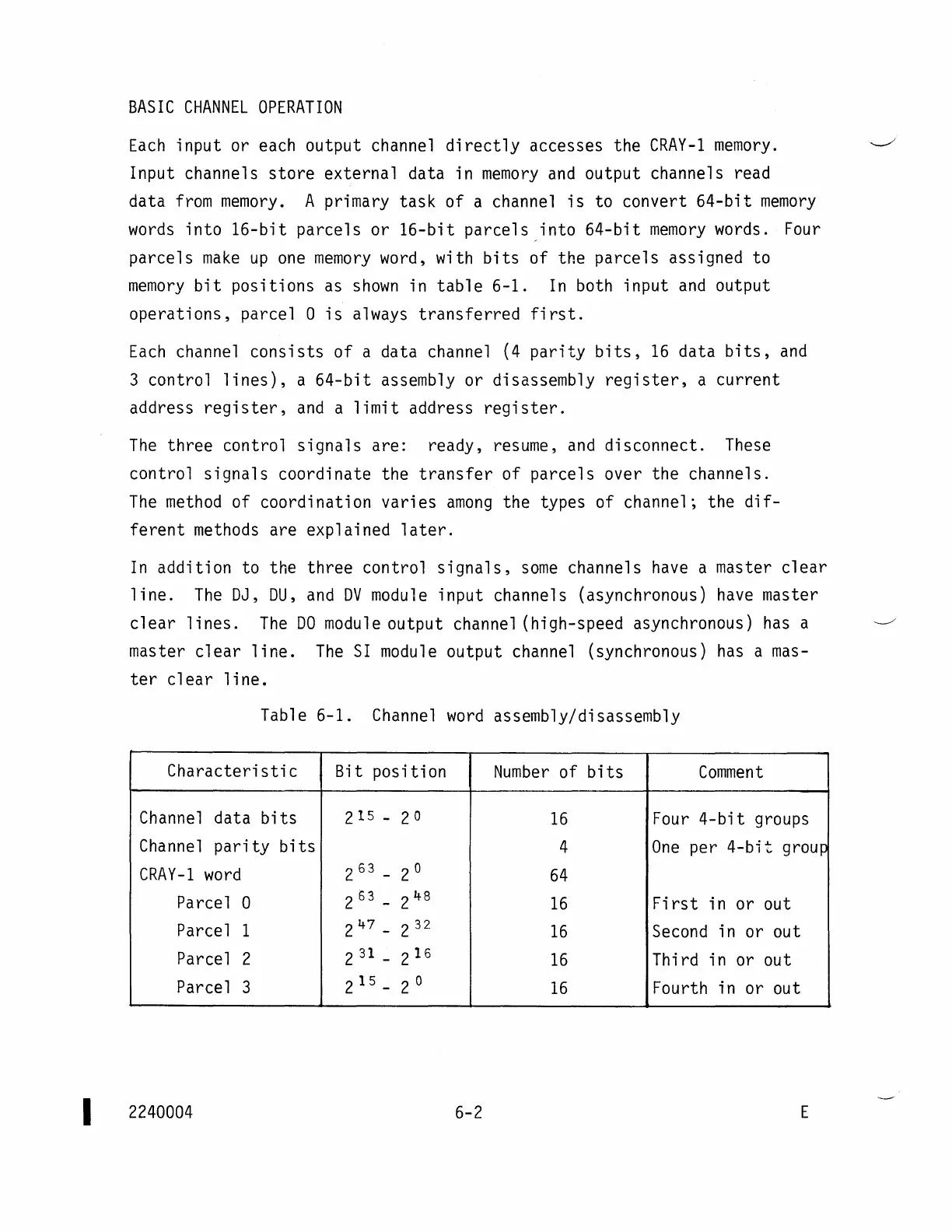
Table 6-1.
Channel
word
assembly/disassembly
Characteristic
Bit position
Number
of
bits
Comment
Channel
data
bits
215 -
2
0
16
Four
4-bit
groups
Channel
parity
bits
4
One
per
4-bit
group
CRAY-1
word
2
63
-
2
0
64
Pa
rce 1
0
2
63
_
2
48
16
First
in or out
Parcel
1
247
_
2
32
16
Second
in or out
Parcel
2
2
31
-
2
16
16
Third in or out
Parcel
3
2
15
_
2 0
16
Fourth in or out
2240004
6-2
E