a...1.t-----
12. 5
ns-----~.l
_I
~I
__
-------'I~
'"_---
~3
ns
~
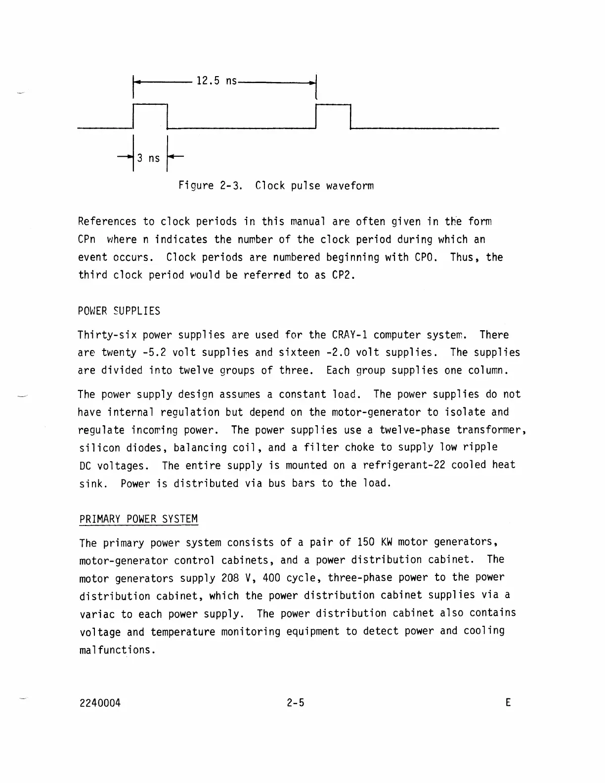
Figure 2-3.
Clock
pulse
waveform
References to clock periods in
this
manual
are often given in the
form
ePn
where
n indicates the
number
of the clock period during
which
an
event occurs.
Clock
periods are
numbered
beginning with
CPO.
Thus, the
third
clock period
~'ould
be
referred to
as
CP2.
PO~JER
SU
PPL
I
ES
Thirty-six
power
supplies are
used
for the
CRAY-1
computer system.
There
are twenty -5.2
volt
supplies
and
sixteen -2.0 volt supplies.
The
supplies
are divided into twelve groups of three.
Each
group
supplies
one
column.
The
power
supply design
assumes
a constant load.
The
power
supplies
do
not
have
internal regulation but
depend
on
the motor-generator to
isolate
and
regulate
inco~ing
power.
The
power
supplies
use
a twelve-phase transformer,
silicon
diodes, balancing
coil,
and
a
filter
choke
to supply
low
ripple
DC
voltages.
The
entire
supply
is
mounted
on
a refrigerant-22 cooled heat
sink.
Power
is
distributed
via
bus
bars to the load.
PRIMARY
POWER
SYSTEM
The
primary
power
system consists of a pair of
150
KW
motor
generators,
motor-generator control cabinets,
and
a
power
distribution
cabinet.
The
motor
generators supply
208
V,
400
cycle, three-phase
power
to the
power
distribution
cabinet,
which
the
power
distribution
cabinet supplies via a
variac to each
power
supply.
The
power
distribution
cabinet also contains
voltage
and
temperature monitoring equipment to
detect
power
and
cooling
malfunctions.
2240004
2-5
E