Cybex 425T Treadmill Service Manual
Service
Page 4-14
8. Remove the black brush assembly.
A. Using a large flat head screwdriver pry out the brush retainer on the drive motor that
secures the black wire. The brush and spring will pop out.
9. Examine the brush and commutator.
A. Inspect the commutator by looking through the top brush holder into the motor. Slowly spin
the motor by turning the flywheel. Look for noticeable damage and for signs of wear such
as arcing, pitting, burning, or uneven wear. Commutator bars that are ‘dirty penny’ brownish
copper are in great condition. Also, some commutator bars may be pitted or blackened
on one edge. Too many of these indicate a worn commutator, and the motor should be
replaced. The commutator may be cleaned with narrow commutator stone if carbon
build-up is present. Brush dust can be loosened from the motor surfaces where the brush
is placed by lightly filing the surfaces. Dirt and brush dust should be vacuumed out of the
motor.
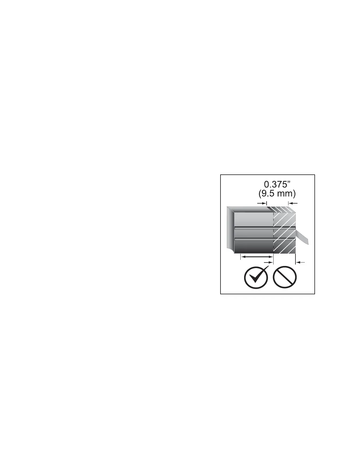
B. Inspect the brushes for signs of excessive wear or
cracks. The motor brushes must be replaced if one
or both is worn to .375” (9.5 mm) or less in length, is
broken or chipped, has a broken spring, or binds in
the motor. See Figure 13.
10. Replace the black brush assembly.
A. Slide the new brush into the motor brush holder. If
the new brush does not slide in and out easily, the
edges or corners of the brush can be lightly filed
down. If cleaning the motor, (see step 9A), and filing
the brush doesn’t allow the brush to slide easily in
the brush holder, the motor should be replaced.
NOTE: The motor may make a clicking noise as new
brushes wear in. If you reinstall the original brushes
it is good to install them facing their original position.
Reversing the orientation of the brush can cause a
clicking noise during operation until the brushes wear in.
B. Fully compress the spring by pushing as far into the brush holder as possible.
C. While compressing the spring, place the new brush retainer into the motor housing until
the brush retainer is fully seated into the motor housing.
D. Repeat steps 8A to 10C for the red brush assembly.
11. Connect the drive motor cables.
A. Place the new drive motor cables into the wire clamp retainer at the end of the motor.
B. Using the 7/16” open end wrench tighten the nut securing the drive motor cables in the
wire clamp retainer.
Figure 13
 Loading...