Cybex 425T Treadmill Service Manual
Service
Page 4-34
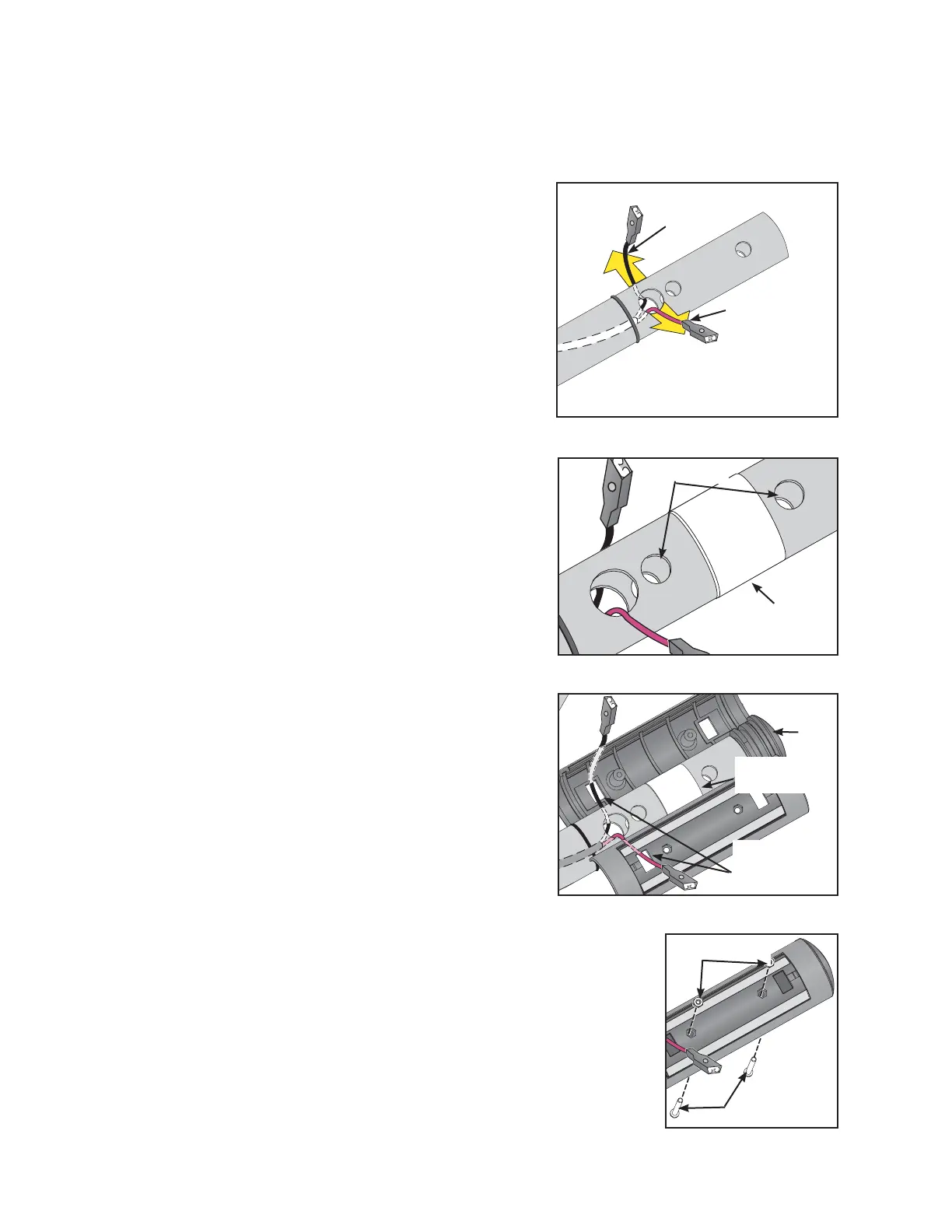
21. Route the new contact heart rate cable.
A. Connect the contact heart rate connector into the bottom of the heart rate board. See
Figure 22.
B. Locate the short and long side of the heart rate
cable.
C. Route the short cable end to the left (from
treadmill user’s viewpoint) and the long end to
the right.
D. Fold the each cable and place it into the hole
that leads to the grip. See Figure 30.
E. Push each wire out a hole (red out the front hole
and black out the back hole). See Figure 30.
22. Secure the new plastic housing.
A. Remove the protective paper from the loose
pieces double-sided tape and stick each one
between two small holes in the handrail. See
Figure 31.
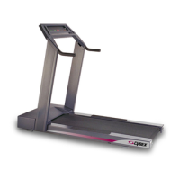
B. Position each set of plastic housing so that
the grooves fit together snugly. NOTE: If the
grooves
don’t fit and the housing gets taped down in the
wrong position pulling it up will destroy the tape.
Do not let the plastic housing touch the double-
sided tape until step 7E.
C. Place each plastic grip near the handrail and
pull each wire through a rectangular hole. See
Figure 32. NOTE: Don’t let the wires slip back
into their holes.
D. Fit the three plastic parts in position (the housing
(2) and the cap (1)) and continue holding all
plastic parts through the next step. See Figure
32.
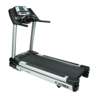
E. While being careful not to overtighten and crack
the housing, place the nuts in their holes and secure them
with the bolts. NOTE: It is easier to place the nuts on the top
and the bolts from the bottom. See Figure 33.
Figure 33
Nuts
Bolts
Figure 32
Wire Through
Rectangular
Hole
Cap
Double-sided
Tape
NOTE: Front is from treadmill
user’s viewpoint.
Red Wire
(Front)
Black Wire
(Back)
Figure 30
Figure 31
Double-sided
Tape
Small Holes