DGS-3100 Series Gigabit Stackable Managed Switch Hardware Installation Guide
1
IDENTIFYING EXTERNAL COMPONENTS
This chapter describes the front panel, rear panel, side panels, and LED indicators of the DGS-3100 Series. This section
contains the following topics:
•
Viewing the Front Panel
•
Viewing Rear Panel
•
Side Panels
•
LED Indicators
Viewing the Front Panel
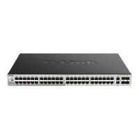
The front panels of the switches consist of LED indicators, 8/24/48 1000BASE-T ports, four mini-GBIC combo ports, and
16 SFP ports.
Figure 1-1 DGS-3100-24P Front Panel View
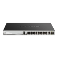
Figure 1-2. DGS-3100-48 Port Front Panel View
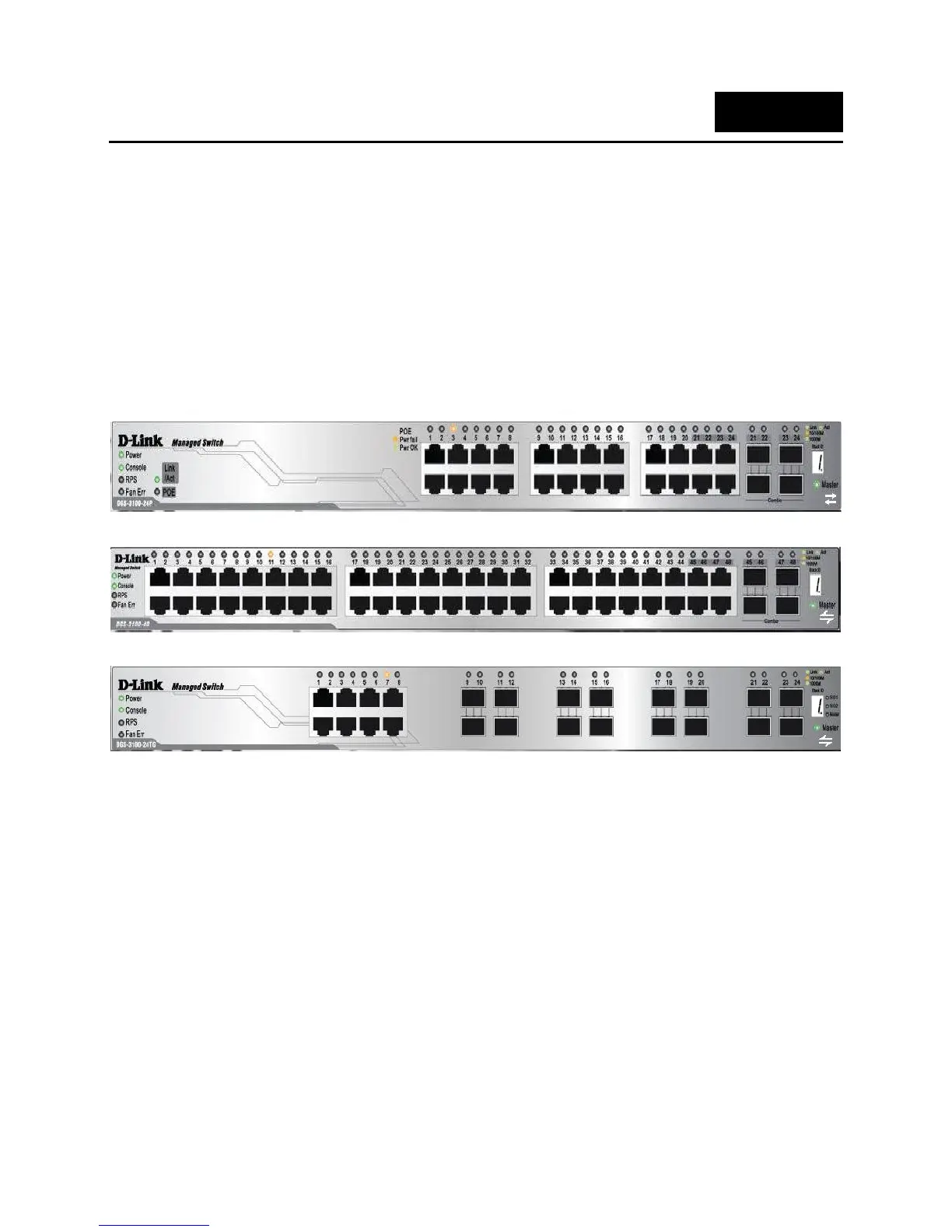
Figure 1-2 DGS-3100-24TG Front Panel View
• Comprehensive LED indicators display the status of the switch and the network (see the LED Indicators section
below).
• Eight/Twenty-four/Forty-eight 1000BASE-T Ethernet ports for 10/100/1000 connections to a backbone, end
stations, and servers.
• Four mini-GBIC combo ports to connect fiber optic media to another switch, server, and core router switch, or
network backbone.
• The DGS-3100-24TG device contains 16 SFP ports to connect fiber optic media to another switch, server, and core
router switch, or network backbone
• A Restore Default Button that is used to restore default settings. To restore defaults settings the button must be held
down for five seconds.
1

 Loading...