EasyManuals Logo

D-Link DGS-3100 SERIES Hardware Installation Guide

D-Link DGS-3100 SERIES
54 pages
To Next Page IconTo Next Page
To Previous Page IconTo Previous Page
Page #14 background imageLoading...
Page #14 background image
DGS-3100 Series Gigabit Stackable Managed Switch Hardware Installation Guide
LED Indicators
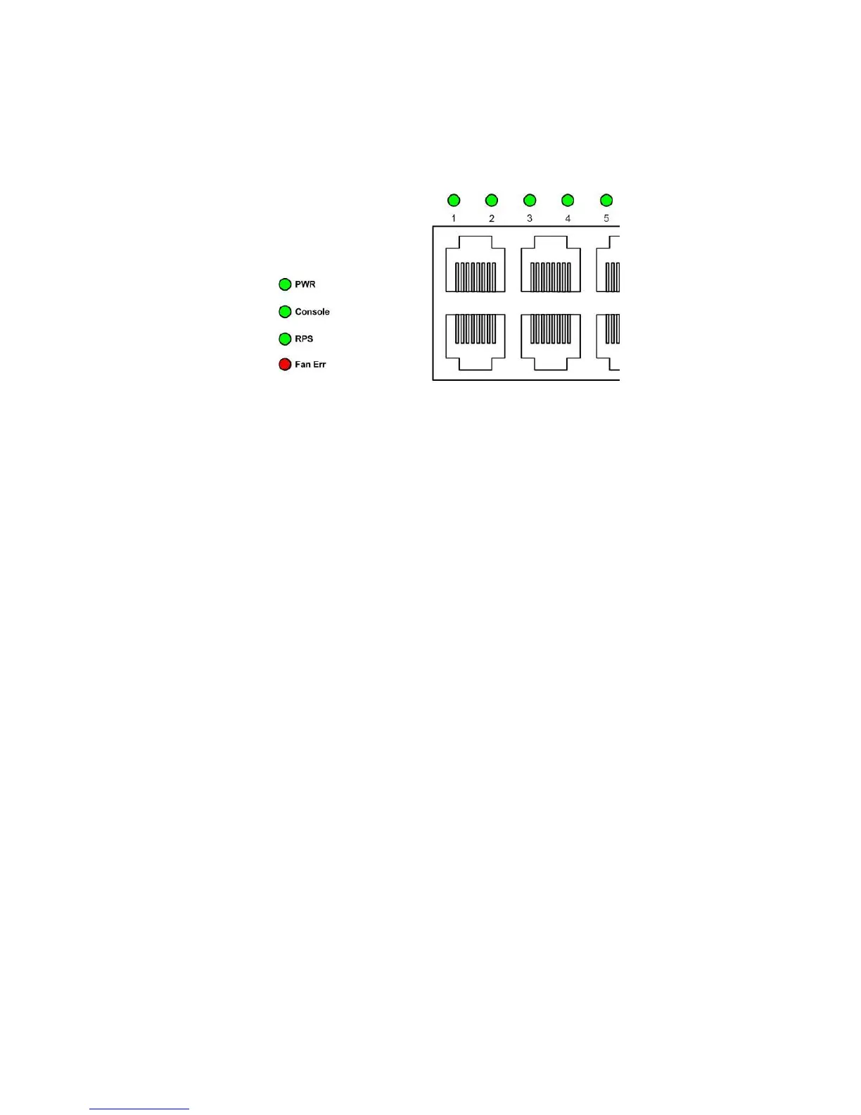
The LED indicators of the switch include Power, Console, RPS, Speed, and Link/Activity. The following figure shows the
LED indicators for the switch along with an explanation of each indicator.
Figure 1-6. LED Indicators
PWR – Located on the front panel, the indicator is a solid green light when the system is powered up, and remains
dark when the system is off.
Console – This indicator flashes green when the system is booting up. It remains solid green when the system is
operating properly. The LED is solid amber when the POST fails.
RPS – This indicator is solid amber when the external Redundant Power Supply is on, and remains dark when it is
not in use or the main power supply is working.
Fan Err –This indicator flashes red when any fans fail. The indicator remains dark (off) when all fans work
normally.
4

Table of Contents

Other manuals for D-Link DGS-3100 SERIES

Questions and Answers:

Question and Answer IconNeed help?

Do you have a question about the D-Link DGS-3100 SERIES and is the answer not in the manual?

D-Link DGS-3100 SERIES Specifications

General IconGeneral
TypeManaged
LayerLayer 2+
Ports10/100/1000BASE-T
SFP Ports2 or 4 (depends on the model)
Additional SFP PortsNo
VLANsYes
StackingYes, Physical Stacking
QoSYes
Jumbo Frame SupportUp to 9K bytes
ManagementWeb-based
Operating Temperature0°C to 40°C
Humidity10% to 90% non-condensing
Standards ComplianceIEEE 802.3, IEEE 802.3u, IEEE 802.3ab, IEEE 802.3z, IEEE 802.3x, IEEE 802.1D, IEEE 802.1w, IEEE 802.1s, IEEE 802.1Q, IEEE 802.1p
ModelDGS-3100 SERIES
Storage Temperature-40°C to 70°C

Related product manuals