EasyManuals Logo

D-Link DGS-3100 SERIES Hardware Installation Guide

D-Link DGS-3100 SERIES
54 pages
To Next Page IconTo Next Page
To Previous Page IconTo Previous Page
Page #13 background imageLoading...
Page #13 background image
DGS-3100 Series Gigabit Stackable Managed Switch Hardware Installation Guide
Side Panels
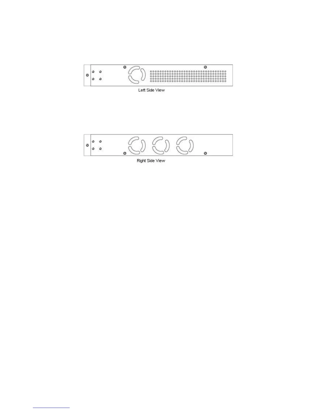
The right side panel of the switch contains two system fans (see the top part of the diagram below). The left side panel
contains heat vents.
Figure 1-5. Side Panel Views of the Switch
The system fans dissipate heat, and the heat vents located on the sides serve the same purpose. The openings must remain
clear of obstructions. Ensure there is at least 6 inches of clear space at the rear and sides of the switch for proper ventilation.
System components can overheat, which potentially, can lead to system failure without proper heat dissipation and air
circulation.
The number of fans on the devices are:
DGS-3100-24 & DGS-3100-24TG – 2 fans.
DGS-3100-24P, DGS-3100-48 & DGS-3100-48P – 4 fans.
3

Table of Contents

Other manuals for D-Link DGS-3100 SERIES

Questions and Answers:

Question and Answer IconNeed help?

Do you have a question about the D-Link DGS-3100 SERIES and is the answer not in the manual?

D-Link DGS-3100 SERIES Specifications

General IconGeneral
TypeManaged
LayerLayer 2+
Ports10/100/1000BASE-T
SFP Ports2 or 4 (depends on the model)
Additional SFP PortsNo
VLANsYes
StackingYes, Physical Stacking
QoSYes
Jumbo Frame SupportUp to 9K bytes
ManagementWeb-based
Operating Temperature0°C to 40°C
Humidity10% to 90% non-condensing
Standards ComplianceIEEE 802.3, IEEE 802.3u, IEEE 802.3ab, IEEE 802.3z, IEEE 802.3x, IEEE 802.1D, IEEE 802.1w, IEEE 802.1s, IEEE 802.1Q, IEEE 802.1p
ModelDGS-3100 SERIES
Storage Temperature-40°C to 70°C

Related product manuals