Pilot's Operating Handbook
Section 2
Limitations
EASA Approved
Edition 0 - October 31, 2013
Rev. 4
Page 2.8.1
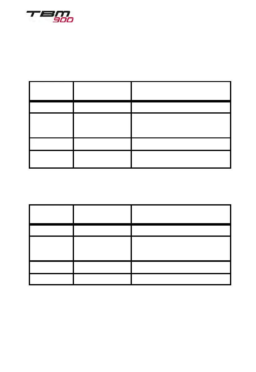
2.8 - Markings
Air
speed indicator on PFD(s)
Markings and their color code significance are shown in figure 2.8.1.
Marking
KIAS
(Value or range)
Significance
Red strip Below 65 /
White strip 65 - 122 Full flap operating range
Lower limit is maximum weight
V
SO
in landing configuration.
Green strip 122 - 266 Normal operating airspeed range
Red/white barber
pole strip
Above 266 266 = VMO
Figure 2.8.1 - Airspeed indicator markings
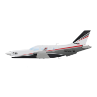
Standby airspeed indicator
Markings and their color code significance are shown in figure 2.8.2.
Marking
KIAS
(Value or range)
Significance
Red strip Below 65 /
White strip 65 - 122 Full flap operating range
Lower limit is maximum weight
V
SO
in landing configuration.
Green strip 122 - 266 Normal operating airspeed range
Red strip 266 Maximum speed for all operations.
Figure 2.8.2 - Standby airspeed indicator markings