Page 10 of 60 IM 817-4
Installing Louvers
Typical Installation Methods
Ifthefreshairopeninghasnotyetbeenmade,seegures9through16
fortherecommendedlocationsandthejob-specicplansfortheexact
location. Follow local codes.
Cut the wall opening so that it is slightly larger than the louver being
installed. For dimensions, see Table 3. If the opening is already there,
measure to be sure there is a minimum of 3/8" (9mm) clearance around
all sides. For masonry installations, a lintel must be installed above
all louvers.
In thick wall applications, the portion of the wall between the louver
and the unit is the outside air plenum. Line this plenum area with 3/8"
(9 mm) mortar or other suitable material. In some applications, the job
specicationsrequireametalsleeveconnectionbetweenthelouverand
the unit. If using such a sleeve, properly caulk it to ensure a weather-
tight seal. This is critical in preventing freeze-ups, cold drafts, and air
inltration.Besurethewallissmooth,square,andprovidesasuitable
mating surface.
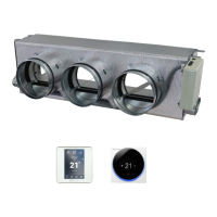
Before setting the louver, construct a sloping, sealed cement mortar base
todrainunwantedmoisturetotheoutside,(seegure17).Besurethe
mortar base is 1" (25mm) thick at the unit and tapers toward the louver.
The mortar at the unit also acts as a backing against which the open
cell gasket of the unit itself can seal. This is critical in preventing water
leaks and air leaks under the unit. Be sure the sealed cement mortar
baseissmoothandushwiththeinteriorwall.
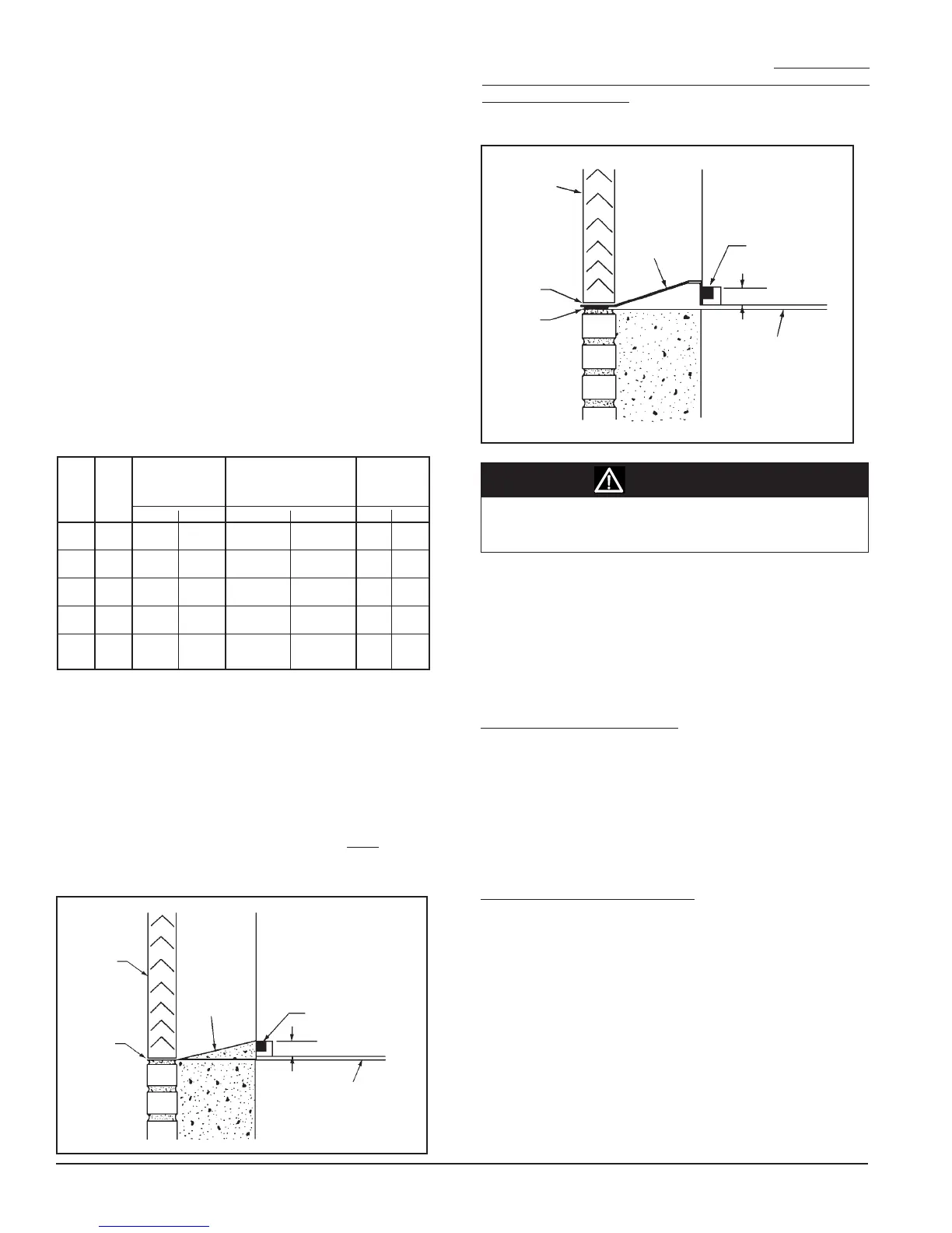
Ifitisnotpossibletoconstructaslopingmortarbase,theneld-supplied
ashingisrequired.Seegure18.Theashingshouldterminateush
with the exterior of the building. Place a bead of caulk undertheashing
to prevent moisture from wicking back to the unit. Do not caulk the
jointbetweenthelouverandtheashing.Thisjointisdesignedtolet
unwanted moisture escape.
Personal injury hazard. Wear protective gloves to avoid possible
cuts and abrasions from exposed edges. Avoid contact with sharp
edges.
Seegures6through19.Beforesettingthelouver,besurethedrain
lip (vertical louver) are at the bottom, horizontal louver blades face
downandthebirdscreenistowardstheunit.Seegures20and21.
Place a heavy bead of caulk along the top and the two vertical sides of
the louver, leaving the bottom uncaulked so that if moisture gets into
the area between the louver and the unit, it can drain to the outside,
unrestricted.
Ifthelouverissuppliedwithanges,(seegure20)placeanadditional
beadofcaulkontheinsideofthetopandsideangesthatcomein
contact with the building facade. Do not caulk the bottom ange.
Place the louver in the opening and push it tight against the supplied
building, fastening it to the exterior of the building using fasteners (by
others) appropriate to the installation. Seal the top and sides with a
waterproof caulk to make it weather-tight. Do not caulk the bottom of
thelouver;doingsomighttrapunwantedmoisturebehindtheange.
(Seegure20)
Ifthelouverissuppliedwithnoanges,(seegure21)placethelouver
in the opening so that it is recessed a minimum 1/16" (2mm) beyond
thebuildingfacadeorasdirectedinthearchitecturalplans.Ifspecied
in the plans, secure the louver in the wall using mechanical fasteners
(suppliedbyothers)appropriatetotheinstallation.(Seegure19for
suggested fastening). With the louver solidly in place, run a bead of
caulk around the perimeter of the louver to seal it weather-tight. Do
not plug the weep holes (horizontal louver) or the drip line (vertical
louver).Thismightrestricttheowofunwantedmoisturetotheoutside
(seegure21)
Seegure18.Ifashingwasusedinsteadoftheslopingmortarbase,
caulktheashingwhereitmeetstheinsideoftheopeningbetweenthe
louver and the unit. This helps prevent moisture from getting under the
ashingandintotheroom.
Louver
No
Caulk
Unit Gasket
Wall
Unit
1" (25mm)
Floor
Caulk
(By
Others)
Flashing
(By
Others)
Figure 18 - Typical Louver Installation with Flashing
Unit Gasket
Sealed Cement
Mortar;
Pitch Away
From Unit
Floor
Wall
Unit
Louver
No
Caulk
1" (25mm)
Figure 17 - Typical Louver Installation with Sloping Sealed Cement
Mortar Base
Table 3 - Recommended Wall Openings For Wall Louvers
Recommended
Maximum Number of VentiMatic
Wall Openings
VentiMatic Shutters Shutter(s)
B C
For Wall Louvers
Which Can Be Mounted Air Capacity
On Standard Louver Maximum
Length Height 24" Shutter 36" Shutter cfm L/s
24" 27" 24
5
⁄
8
"
10
7
⁄
8
"
(610) (659) (613) (267)
1 0 500 236
36" 39" 36
5
⁄
8
" 10
7
⁄
8
"
(914) (991) (918) (267) 0 1 750 354
48" 51" 48
5
⁄
8
" 10
7
⁄
8
"
(1219) (1295) (1222) (267)
2 0 1000 472
60" 63" 60
5
⁄
8
" 10
7
⁄
8
"
(1524) (1600) (1527) (267)
1 1 1250 590
72" 75" 72
5
⁄
8
" 19
7
⁄
8
"
(1829) (1905) (1832) (495)
0 2 1500 708
CAUTION