IM 817-4 Page 27 of 60
Heating – Modulating Valve Piping
Hot Water (or 2-pipe CW/HW) Modulating Valve Piping
Return
Return
Balancing and Shutoff Valve
Shutoff Valve
Supply
Supply
2-way
Modulating
Valve
Unit Coil
Unions
2-way Modulating, Normally Open, Hot Water
or 2-pipe CW/HW Valve Piping (typical)
The 2-way Modulating hot water (or 2-pipe CW/HW) valve is furnished
normally open to the coil. When the valve is de-energized (off) there
isfullowthroughthecoil.Energizingthevalvereducesthevolume
ofwaterowinamodulatingfashion.
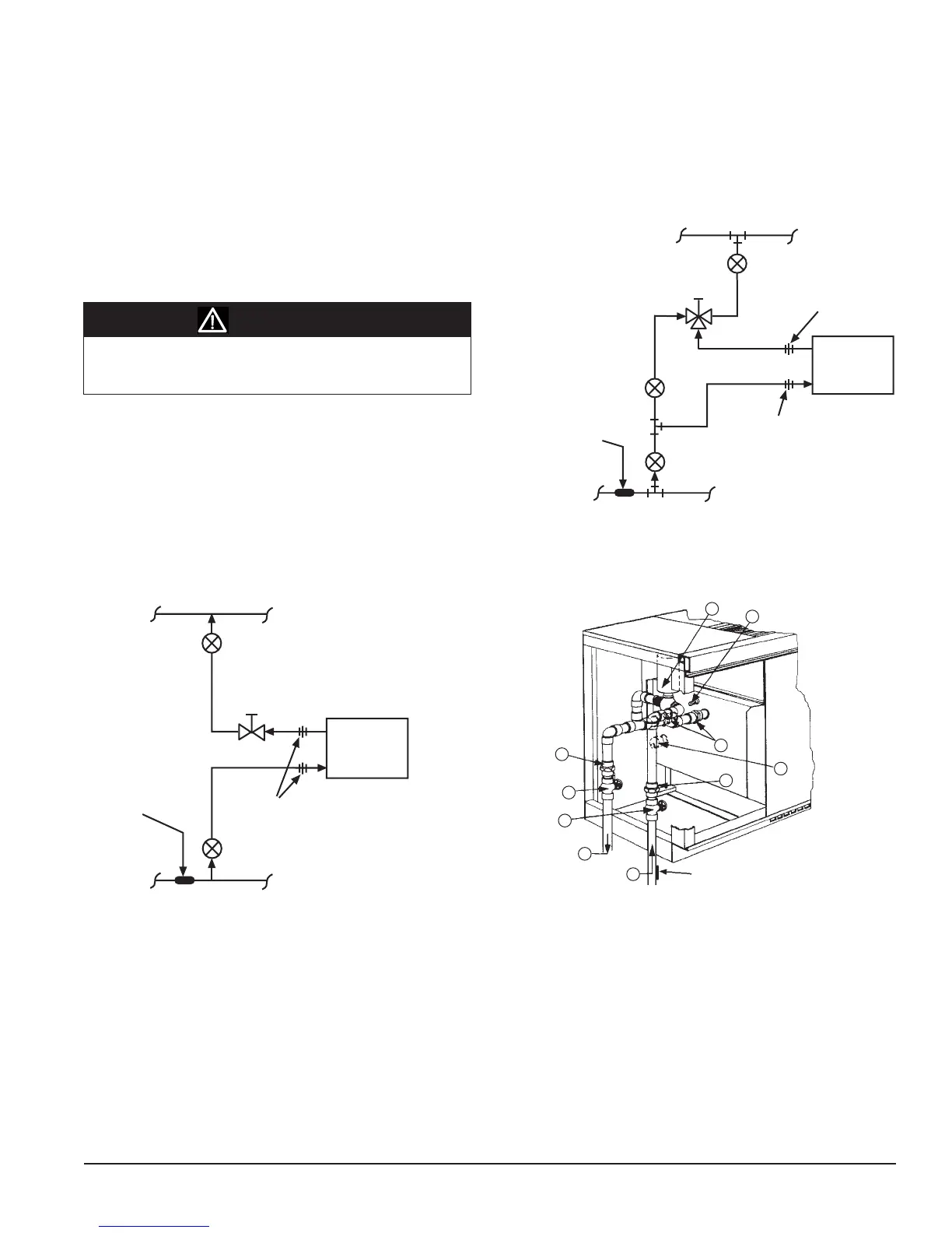
3-way Modulating, Normally Open, Hot
Water or 2-pipe CW/HW Valve Piping (typical)
The 3-way Modulating hot water (or 2-pipe CW/HW) valve is furnished
normally open to the coil. When the valve is de-energized (off) there
isfullowthroughthecoil.Energizingthe valve allows a varying
amount of water to bypass the coil.
Return
Return
Balancing and Shutoff Valve
Shutoff Valve
Supply
Supply
3-way
Modulating
Valve
Unit Coil
Union
Union
Balancing Valve
N.O.
Common
N.C.
When piping the modulating valve, refer to the arrows on the modulating
valvebody to determine thedirectionofow.Thevalveshouldbe
installed so that there is a 2" (51mm) minimum clearance to remove the
actuator form the valve body. Provide unions for removal of unit coil and/
or control valve as a future service consideration. Hot water connections
may be same end as cooling coil connections, but are recommended
to be opposite end to facilitate piping. When using AAF MicroTech II
controls, they must be opposite end. The modulating valve accessory
mustbeeldinstalledontheunitforwhichitwasselected.
S5 Sensor
(2-pipe CW/HW Units Only)
S5 Sensor
(2-pipe CW/HW Units Only)
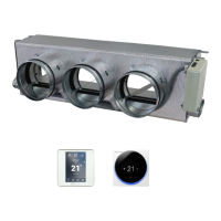
Figure 80 - 3-way Modulating Valve Control
(Piping Outside Unit End Compartment)
2
3
4
5
6
7
15
15
15
11
S5 Sensor
Refer to the arrows on the modulating valve body to determine
the direction of ow. If the valve is mounted improperly, the unit
will not operate properly and damage to the valve may result.
See page 25 for number designation descriptions.
Figure 78 - 2-way Modulating Valve Control, Normally Open, Hot
Water or 2-pipe CW/HW Piping
Figure 79 - 3-way Modulating Valve Control
CAUTION