IM 817-4 Page 33 of 60
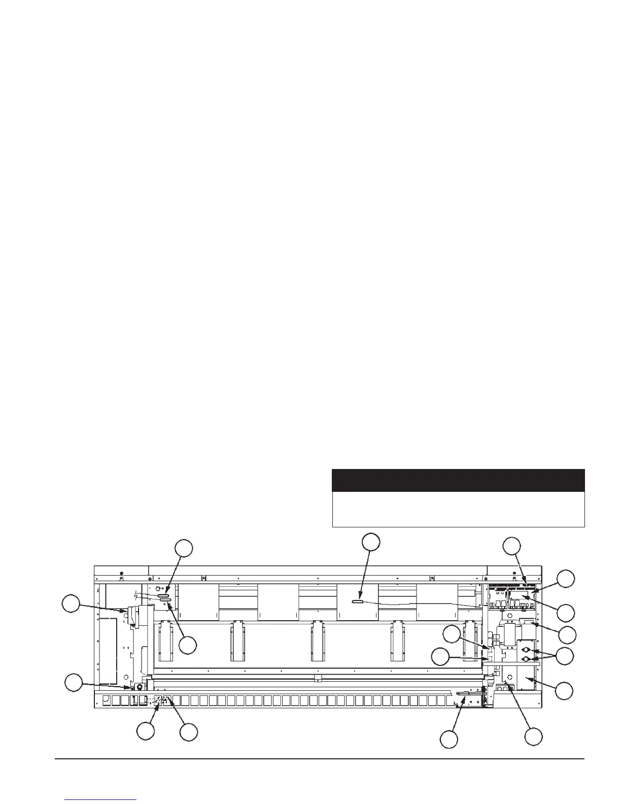
5 Time Clock (TC) (optional on standalone units only) (see g.
94) – Factory mounted 7 day/24 hour, digital time clock with up
to twenty (20) programs to sequence the unit ventilator through
occupied and unoccupied modes in accordance with a user
programmed time schedule.
6 External Signal Connection Plugs: Three (3) multi-pin
plugs are factory provided and pre-wired with short wire
whips that are capped (they must remain capped if not used).
Providedforeldwiringof:
• RemoteWallMountedTemperatureSensor
(optional accessory).
• External Input Signals (by others): unoccupied, remote
shutdown, ventilation lockout, dew point/humidity (night
time operation), or exhaust interlock signals
• External Output Options (by others): lights on/off,
fault indication signal, exhaust fan on/off or auxiliary heat
signal.
7 Electric Connection Box: Contains the motor speed transformer.
Refertotheunitwiringdiagramforspecics.
8 Unit Main Power “On-Off” Switch: (SW1) Disconnects the
main power to the unit for servicing or when the unit is to be shut
down for an extended period of time.
9 Fuse(s) - Fan motor and controls have the hot line(s) protected
by factory installed cartridge type fuse(s).
10 Control Transformer - 75 VA 24-volt NEC Class 2 transformer for
24 volt power supply. (Located behind the motor transformer).
11 Outdoor Air/Return Air Damper Actuator - (A1) Direct coupled,
oatingpoint(tristate)actuatorthatspringreturnstheoutdoorair
damper to the closed position upon a loss of power.
12 Face and Bypass Damper Actuator - (A2) Directcoupled,oating
point (tristate) actuator that is non-spring returned (Model AVS
only).
13 Hydronic Coil Low Air Temperature Limit (T6 freezestat)
– Factory installed on all units with hydronic (water) coils. The
T6 freezestat cuts out at 38
o
F (+/- 3
o
F) and automatically resets
at 45
o
F (+/- 3
o
F).
14 Low Refrigerant Temperature Sensor (S4) - The S4 sensor is
provided on all units with a direct expansion (DX) cooling coil.
Itislocatedontherighthandsideofthecoil“u-bend”.
1 MicroTech II Unit Ventilator Controller (UVC): (Located
Beneath the Local User Interface Panel). Factory mounted and
run tested, microprocessor-based DDC control device capable
of complete Standalone unit control, Master/Servant control or
incorporated into a building-wide network using an optional plug-in
communication module. The UVC contains a microprocessor that
is preprogrammed with the application code required to operate the
unit. The UVC supports up to 6 analog inputs, 12 binary inputs,
and 9 binary outputs. The UVC EXP I/O board supports up to 4
additional analog inputs and 8 additional binary outputs. Master/
Servantunitshavethecontrollerfactoryconguredandinstalled
for a local peer-to-peer network between these units (network
wiringbetweentheseunitsneedstobeeldinstalled).Optional
network communication is provided via plug-in communication
modules that connect directly to the UVC.
2 Communication Module (optional): Plug-in network
communication module that is attached to the UVC via a 12-
pin header and 4 locking standoffs. Available communication
modules:
• Building Automation and Control Network (BACnet
®
)
Master Servant/Token Passing (MS/TP) - Allows the UVC to
inter-operate with systems that use the BACnet (MS/TP) protocol
with a conformance level of 3. Meets the requirements of ANSI/
ASHRAE 135-1995 standard for BACnet systems.
• LonWorks
®
compliant Space Comfort Controller (SCC)
–SupportstheLonWorksSCCprolenumber8500_10.
• Metasys N2
®
Open – Provides N2 Open network
communication capability to the UVC.
3 Local User Interface (LUI): (see g. 93) The LUI provides a unit
mounted interface which indicates the current unit operating state
and can be used to adjust the unit ventilator operating parameters
(operating mode, temperature set points, fan speed and occupancy
mode). The LUI features a 2-digit display, 7 keys (1 key is hidden),
and9individualLEDindicators.See“LocalUserInterface”for
further details.
4 Tenant Override Switch (see g. 94) – Provides a momentary
contactclosurethatcausestheunittoenterthe“tenantoverride”
operating mode for a set time period (default = 120 minutes).
1
2
7
8
9
10
12
11
6
Figure 92 - MicroTech II Sensor and
Component Locations (Front View)
14
13
15
17
18
19
16
20
Making Control Connections
MicroTech
II™ Unit Mounted DDC Control
Components – Models AVS, AVV, and AVR
Not all external signal options can be used simultaneously and
may not be available on all software models. Refer to the “UVC
Input and Output Tables” in IM 739 for available options.
NOTICE