IM 817-4 Page 15 of 60
Meeting IBC Seismic Requirements
Daikinunitventilatorscanbespecied,asfollows,tomeetInternational
Building Code seismic requirements:
•
All components included in these unit ventilators are designed,
manufacturedandindependentlytested,ratedandcertiedtomeet
the seismic compliance standards of the International Building
Code.
•
Components designated for use in systems that are life safety,
toxic, high hazard, combustible or ammable meet the on line,
anchorageandloadpathrequirementsforlifesafetyasdenedin
IBC sections 1621.1.6, 1621.3.3,1707.7.2. and IBC Commentary,
Volume II, section 1621.1.6, IBC notes pertaining to the release of
hazardous material.
•
All components used as part of a system other than the above meet
as a minimum, all load path and anchorage standards for components
as outlined in IBC section 1621.3.3 & 1707.7.2.
•
Allcompletedcomponentassembliesareclearlylabeledforeld
inspection. Seismic Compliance Labels include the manufacturer’s
identication,designationofcertiedmodels,denitiveinformation
describing the product’s compliance characteristics, and the
IndependentCertifyingAgency’snameandreportidentication.
In addition to all seismic requirements for IBC Certication listed
elsewhere in the project specication, submittals for these units
include:
1.
A Certicate of Compliance from the Independent Certifying
Agency clearly indicating that components supplied on this
projectareincludedinthecomponentmanufacturer’sCerticate
of Compliance.
2.
Clear installation instructions including all accessory components
that are part of the overall component installation.
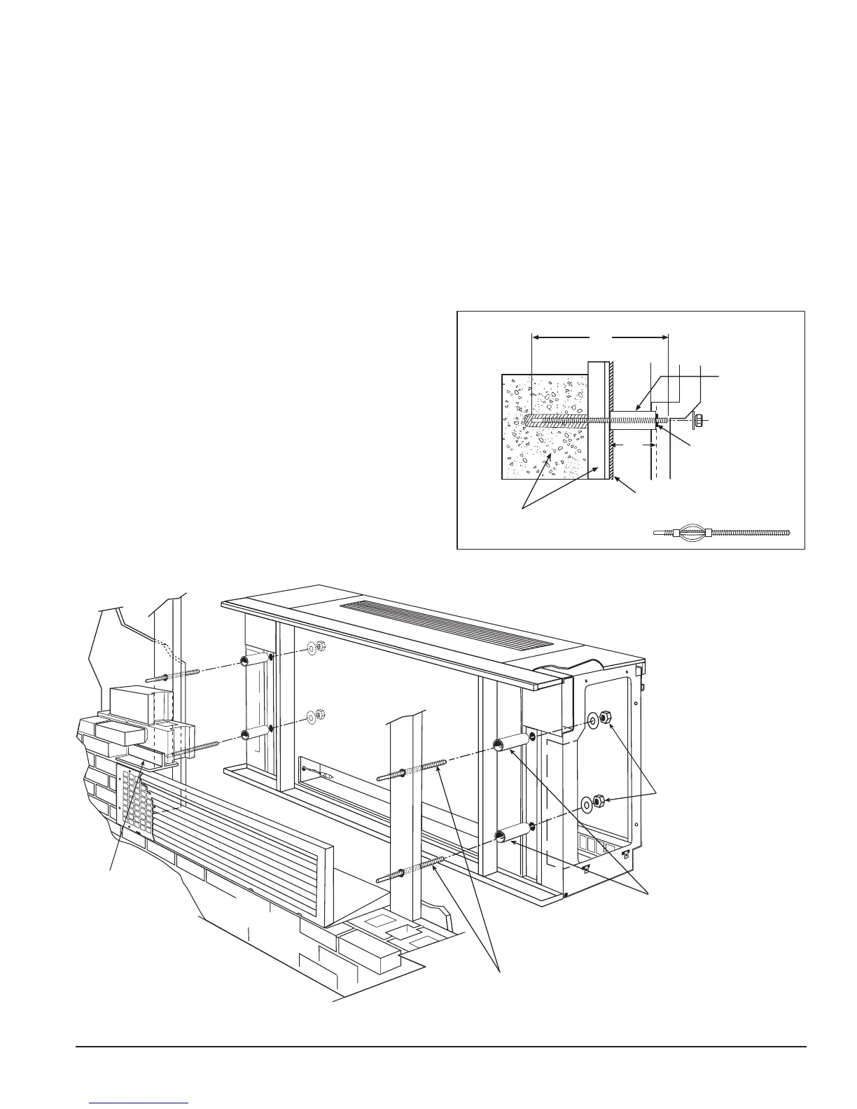
(4) - 3/8" diam. x (dimension “Y”) galvanized
threaded rod (by others) - align with unit
mounting holes, and set into building structure
mortar or structural support column (see detail).
(4) - 1-1/2" O.D. x (dimension “X”),
galvanized steel pipe (by others),
gives rigidity to the unit in relation
with the building structure (see detail).
(4) - 3/8" galvanized nut with
washer (by others), attach from
inside unit end compartments.
Tighten nut until steel pipe is
compressed between unit and
building structure or column.
Lintel
(by others)
Building structure or
support column
Gasket on back of unit
Top mounting hole
on unit frame
1-1/2" O.D.
galvanize
steel pipe
Y
X
NOTE: Dimensions “X” and “Y” to be determined by installing
contractor based on fit up requirements of job.
*A Molly or Toggle bolt may be necessary if voids in the building
structure or support columns are present.
*
DETAIL
Figure 34 - Typical IBC Seismic Installation