IM 817-4 Page 19 of 60
Face and Bypass Valve
First Position in Air Stream Second Position in Air Stream AVS AVS Elect.. AVV AVV Elect.
F U D E 00 X X
65 66 67 V S X X
65 66 W X X
65 66 67 G X X
G 12 13 X
V S W 12 13 X
V S W 12 X
G V S 68 69 78 79 X X
65 Y X X
Heating Coils
65 = 1-Row Hot Water Coil
66 = 2-Row Hot Water Coil
67 = 3-Row Hot Water Coil
68 = Low Capacity Steam Coil
69 = High Capacity Steam Coil
78 = Opposite End Drain Low Capacity Steam Coil
79 = Opposite End Drain High Capacity Steam Coil
12 = Low Electric Heat Coil
13 = High Electric Heat Coil
00 = None
Chilled Water and Heating Coils
See Notes and Tables 6 and 7 on page 18
Table 8 - Heat/Cool Position/Combinations In Air Stream (one coil per position) Note: X indicates Available.
Cooling Coils
U = 2-Row CW/HW 2-Pipe Coil
D = 3-Row CW/HW 2-Pipe Coil
E = 4-Row CW/HW 2-Pipe Coil
F = 5-Row CW/HW 2-Pipe Coil
V = 2-Row CW Coil
S = 3-Row CW Coil
W = 4-Row CW Coil
Y = 5-Row CW Coil
G = Direct Expansion Coil
Y = 5-Row CW Coil
Left Hand
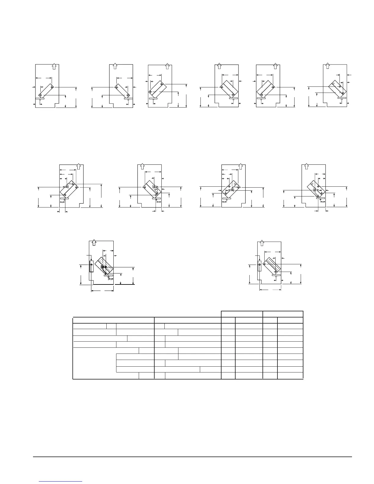
Figure 47 - Chilled/Hot Water (2-pipe) Unit
(Coils D, E, U)
Figure 48 - Chilled Water and Hot Water Unit
(Cooling Coils S, W, V) (Heating Coils 65, 66, 67)
Figure 49 - Chilled Water and Steam Unit
(Cooling Coils S, V)
(Heating Coils 68, 69, 78, 79)
Figure 50 - Direct Expansion (G) and Hot Water Unit
(Cooling Coil G) (Heating Coils 65, 66, 67) (Not Reheat)
Figure 51 - Direct Expansion (G) and Steam Unit
(Cooling Coil G) (Heating Coils 68, 69, 78, 79)
Figure 52 - Direct Expansion and Electric Heating
(Cooling Coils G) (Heating Coils 12, 13)
Right Hand
Right Hand
(Cooling) Left Hand
(Heating) Right Hand
Figure 53 - Chilled Water (1st Position) and Electric Heating
(Cooling Coils V, S, W) (Heating Coils 12,13)
Right Hand
Note: For opposite end drain steam coils (code 78,79) Return (R) is 7
1
⁄
4
" (184mm) from bottom of unit and H - 2" (51mm) from back of unit. (see
table 6 for dimensions)
Coil Headers, Locations
Direct Expansion Coils and Heating Coils (See Table 7 for Direct Expansion (DX) Coil)
(Cooling) Left Hand
(Heating) Right Hand
(Cooling) Left Hand
(Heating) Right Hand
(Cooling) Left Hand
(Heating) Right Hand
14"
(356mm)
L
Junction Box
LL
SL
J
D
C
7-1/4"
(184mm)
Air Flow
11-3/4"
(299mm)
S = Supply
R = Return
S = Supply
R = Return
S
= Supply
R = Return
R
S
J
A
B
B
8-1/2"
(216mm)
13-3/4"
(349mm)
J
A
13-3/4"
(349mm)
8-1/2"
(216mm)
Air Flow
Air Flow
R
S
CW Coil
R
S
13-3/4"
(350mm)
A
B
J
8-1/2"
(216mm)
R
S
16-1/8"
(410mm)
E
F
J
11"
(279mm)
HW Coil
Air Flow
Air Flow
St eam
R
S
13-3/4"
(350mm)
J
8-1/2"
(216mm)
R
S
16-1/8"
(410mm)
A
B
J
11"
(279mm)
CW Coil
K
H
Air Flow
Air Flow
LL
SL
14-1/4"
(368mm)
J
9-3/4"
(248mm)
R
S
8-1/2"
(216mm)
Air Flow
13-3/4"
(349mm)
LL
SL
14-1/4"
(368mm)
J
B
R
S
A
Air Flow
16-1/8"
(410mm)
I
8-1/2"
(216mm)
B
F
A
G
13-3/4"
(349mm)
I
LL
SL
14-1/4"
(368mm)
J
10-1/8"
(257mm)
D
C
R
S
H
K
7-1/4"
(184mm)
Air Flow
11-3/4"
(299mm)
LL
SL
14-1/4"
(368mm)
J
B
R
S
H
K
10-1/8"
(257mm)
Air Flow
13-3/4"
(349mm)
11-3/4"
(299mm)
D
R
S
13-3/4"
(350mm)
A
B
J
8-1/2"
(216mm)
Air Flow
14"
(356mm)
L
Junction Box