IM 817-4 Page 39 of 60
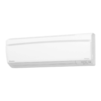
Wire Wips for Field
Wiring with Caps
(see the wiring
diagram provided
on the unit ventilator
right front access
panel)
Field Wiring at
back of Local User
Interface (LUI)
Panel
Figure 102 - Model AV - Field Wiring Whips with Caps Viewed from
Right End Compartment
Two pin plug for unit mounted
sensor
Field Wiring Remote Mounted Temperature
Sensor
Thelowvoltageeldwiringconnectionshaveallbeencentrallylocated
within the unit ventilator and are easily accessible.
Tosimplifyeldconnections,multi-pinplugsarefactoryprovidedand
pre-wiredwithshortwirewhips(seegure102).Eachofthewiresin
these wire whips is capped and should remain capped if not used. The
unit mounted temperature sensor is provided with a quick disconnect
plug (white) with wires numbered 102 and 103, and must be separated
so that the unit mounted sensor is disconnected from the UVC. This
disables the unit mounted sensor (see gure 102). See Figures 103
and 104 for wiring the remote mounted temperature sensor to the unit
control wiring.
Alllowvoltageeldwiringconnectionsmustberuninshieldedcable
with the shield drain wires connected as shown in the eld wiring
diagrams.
Installing the Remote Mounted Temperature
Sensor
This describes the installation of the following three wall mounted
sensor models:
• P/N111048101–Basic
• P/N111048103–Expanded±3
o
F setting
• P/N111048102–Deluxe54
o
F to 85
o
F setting
Use the installation instructions included with the Remote wall
sensor.
Parts Included - All Models
• pre-assembledsensorthatincludes:
- large (50.8 x 101.6 mm [2 x 4 in.]) mounting base (1)
- terminal block (1)
- 1.5 mm (1/16 in.) cover screw (1)
- endcaps (2)
• alternatesmall(80x80mm[3.15x3.15in.])mounting
base (1) with attached terminal block (1)
• coversliderinsertwithprintedlogosforMcQuay
®
(1)
and AAF
®
(1)
• No.6-32x1in.at-headscrew(2)
• No.8x1.25in.panheadtappingscrew(2)
• hollowplasticwallanchor(2)
Parts Included - 111048102 and 111048103 Only
• alternateserratedsetpointdial(attached)
• smoothsetpointdial(separate)
Special Tools Needed
• .5mm(1/16in.)Allenwrench
• 7mm(1/4in.)at-bladescrewdriver
• holesawwith35mm(1-3/8in.)blade(forsurfacemounting
only)•
• drillwith8mm(5/16in.)drillbit(forsurfacemountingonly)
The unit comes with a unit mounted sensor and does not require
a remote wall mounted sensor.
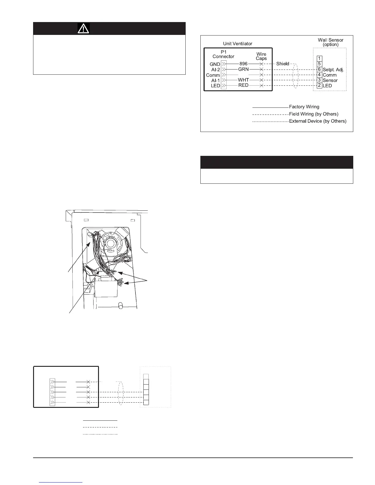
Figure 104 - Wall Mounted Temperature Sensor Wiring for Expanded
and Deluxe Wall Sensor
Static sensitive components. A static discharge while handling
electronic circuit boards can cause damage to the components.
Discharge any static electrical charge by touching the bare metal
inside the main control panel before performing any service work.
Never unplug any cables, circuit board terminal blocks, relay
modules, or power plugs while power is applied to the panel.
Figure 103 - Wall Mounted Temperature Sensor Wiring for Basic Wall
Sensor
896
P1
Connector
BLK
WHT
RED
Wire
Caps
Unit Ventilator
LED
Comm
AI-1
AI-2
GND
6
4
3
2
5
1
Setpt. Adj.
Comm
Sensor
LED
Wall Sensor
(option)
Shield
Field Wiring (by Others)
External Device (by Others)
Factory Wiring
GRN
CAUTION
NOTICE