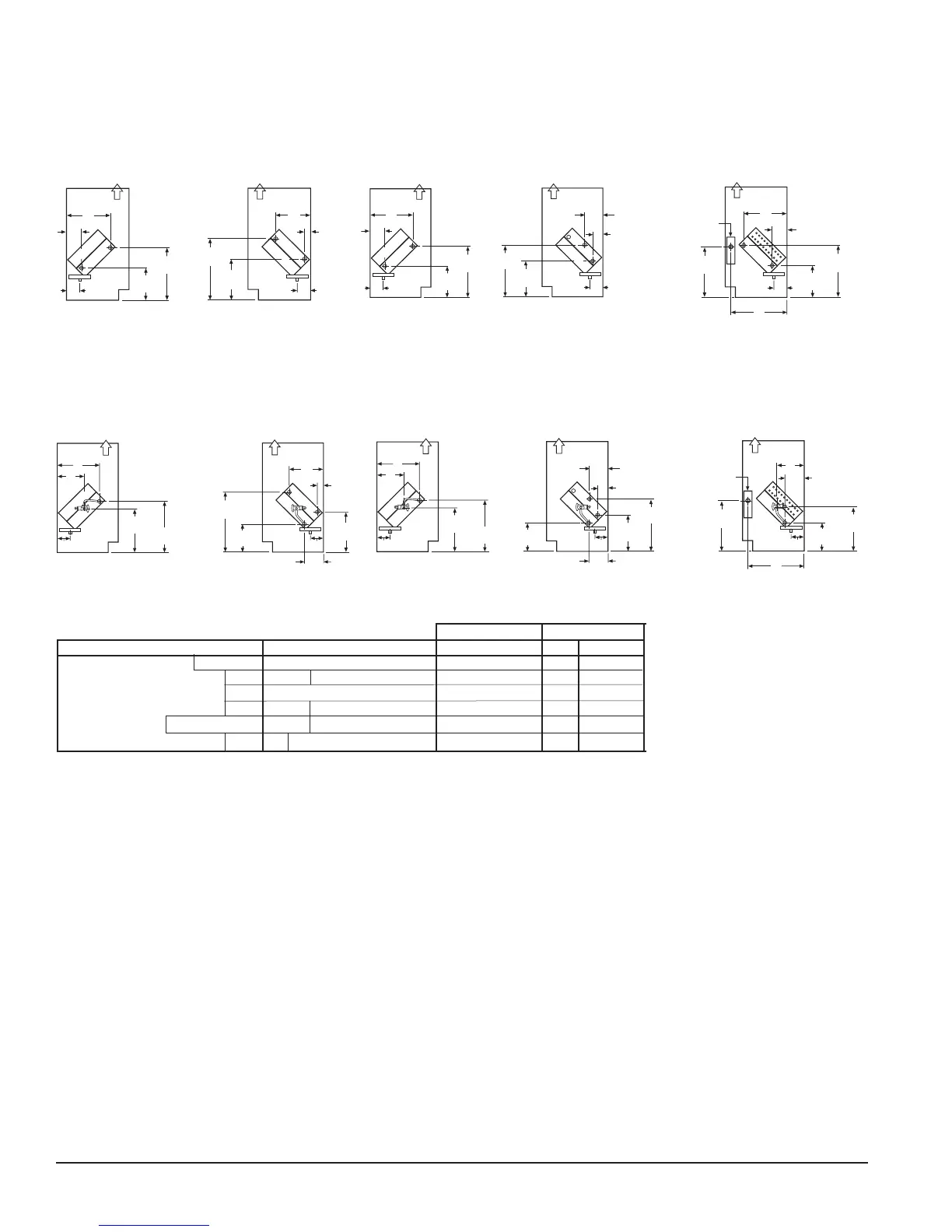
Page 20 of 60 IM 817-4
LL
SL
J
C
7-1/4"
(184mm)
Air Flow
LL
SL
J
B
Air Flow
13-3/4"
(349mm)
11-3/4"
(299mm)
D
HW Coil
R
S
16-1/8"
(410mm)
E
F
11"
(279mm)
St eam
R
S
13-3/4"
(350mm)
J
8-1/2"
(216mm)
R
S
16-1/8"
(410mm)
A
B
J
11"
(279mm)
CW Coil
K
H
Air Flow
Air Flow
Face and Bypass Valve
First Position in Air Stream Second Position in Air Stream AVB AVR AVR Elect.
V S 65 66 67 68 69 78 79 X X
W 65 66 X X
G 65 66 67 68 69 78 79 X
G 12 13 X
V S W 12 13 X
Y 65 X X
Reheat
Table 9 - Reheat Coil Position/Combinations In Air Stream (one coil per position) Note: X indicates Available.
Heating Coils
65 = 1-Row Hot Water Coil
66 = 2-Row Hot Water Coil
67 = 3-Row Hot Water Coil
68 = Low Capacity Steam Coil
69 = High Capacity Steam Coil
78 = Opposite End Drain Low
Capacity Steam Coil
79 = Opposite End Drain High
Capacity Steam Coil
12 = Low Electric Heat Coil
13 = High Electric Heat Coil
Cooling Coils
V = 2-Row CW Coil
S = 3-Row CW Coil
W = 4-Row CW Coil
Y = 5-Row Coil
G = Direct Expansion Coil
Figure 57 - Direct Expansion (G) and
Hot Water Unit (Cooling Coil G)
(Heating Coils 65, 66, 67)
Figure 58 - Direct Expansion (G) and
Steam Unit (Cooling Coil G)
(Heating Coils 68, 69, 78, 79)
Figure 54 - Chilled Water and Hot Water Unit
(Cooling Coils S, W, V)
(Heating Coils 65, 66, 67)
Figure 55 - Chilled Water and Steam Unit
(Cooling Coils S, V)
(Heating Coils 68, 69, 78, 79)
Figure 56- Chilled Water and Electric
Heating (Cooling Coils V, S, W)
(Heating Coils 12, 13)
Figure 59 - Direct Expansion and
Electric Heating (Cooling Coils G)
(Heating Coils 12, 13)
S = Supply
R = Return
S = Supply
R = Return
LL = Liquid Line
SL = Suction Line
Right Hand
Right Hand
Note: For opposite end drain steam coils (code 78,79) Return (R) is 7
1
⁄
4
˝ (184mm) from bottom of unit and H - 2˝ (73mm) from back of unit.
Coil Headers, Locations
S = Supply
R = Return
S = Supply
R = Return
LL = Liquid Line
SL = Suction Line
(Cooling) Left Hand (Heating) Right Hand (Cooling) Left Hand
(Heating) Right Hand
(Cooling) Left Hand
(Heating) Right Hand
(Cooling) Left Hand
(Heating) Right Hand
R
S
13-3/4"
(350mm)
A
B
J
8-1/2"
(216mm)
Air Flow
14"
(356mm)
L
Junction Box
LL
SL
J
7-1/4"
(184mm)
Air Flow
LL
SL
J
B
Air Flow
13-3/4"
(349mm)
11-3/4"
(299mm)
D
Steam
R
S
16-1/8"
(410mm)
11"
(279mm)
K
H
14"
(356mm)
L
Junction Box
LL
SL
J
D
C
7-1/4"
(184mm)
Air Flow
11-3/4"
(299mm)
CW Coil
R
S
A
B
J
R
S
E
F
J
16-1/8"
(410mm)
11"
(279mm)
HW Coil
13-3/4"
(350mm)
8-1/2"
(216mm)
Air Flow
Air Flow