IM 817-4 Page 23 of 60
Valve Inlet Pressure
Cv Connection 2 psig 5 psig 13.8 kPa 34.5 kPa
Capacity Range (MBh) Capacity Range (kW)
0.73 1/2" (13mm) FNPT 11 14 18 22 3.2 4.0 5.2 6.3
1.8 1/2" (13mm) FNPT 27 34 44 53 7.8 9.9 12.9 15.6
4.6 1/2" (13mm) FNPT 68 86 112 136 20.1 25.2 32.9 39.9
7.3 3/4" (19mm) FNPT 109 137 178 216 31.8 40.0 52.2 63.3
11 1" (25mm) FNPT 164 206 269 325 48.0 60.3 78.7 95.4
18.5 1 1/4" (32mm) FNPT 275 346 452 547 80.7 101.4 132.4 160.4
Steam Modulating Valve Selection (MicroTech
II™)
The steam modulating control valve is expected to vary the quantity of
steam through the coil. Any movement of the valve stem should produce
somechangeinthesteamowrate.Toselectamodulatingsteamvalve:
1. Obtain the supply steam inlet pressure.
2. Determine the actual heat requirement of the space to be heated.
3. Select a valve (Cv) from Table 18, which gives the capacity range
based on a 60% pressure drop at the low end of the range and
100% pressure drop at the high end of the range. For example:
With 2 psig (13.8 kPa) inlet steam pressure, the valve with a Cv
of 4.6, in the full open position, would have a 1.2 psig (8.3 kPa)
pressure drop at 68 MBh (20.1 kW) and a 2psig pressure drop at
86 MBh (25.2 kW). The valve should have a capacity less than
or equal to the space to be heated.
Table 18. Modulating 2-Way, Normally Open, Steam Valve – Pressure Drop
Hot Water and Chilled Water Modulating Valve
Selection (MicroTech II)
The unit ventilator control valve is expected to be able to vary the
quantityofwaterthatowsthroughthecoilinamodulatingfashion.
Any movement of the valve stem should produce some change in the
amountofwaterthatowsthroughthecoil.Oversizedcontrolvalves
cannot do this. For example, assume that when the control valve is
fully open, the pressure drop through the coil is twice as great as the
drop through the valve. In this case, the control valve must travel to
approximately50%closedbeforeitcanbegintohaveanyinuence
onthewaterowthroughthecoil.Thecontrolsystem,nomatterhow
sophisticated, cannot overcome this. Oversized control valves can also
resultin“hunting”whichwillshortenthelifeofthevalveandactuator
and possibly damage the coil.
To correctly select the proper Hot Water or Chilled Water Modulating
Valve:
1.Determinetheowofwaterandthecorrespondingpressuredrop
through the coil.
2. Obtain the pressure difference between the supply and return
mains.
3. Select a valve size (Cv) from Table 19 on the basis of taking 50%
oftheavailablepressuredifference(atdesignow)betweenthe
supply and return mains at the valve location. The valve should
have a pressure drop greater than that of the coil.
4. Select a normally open valve for hot water, or 2-pipe CW/HW
coils. For chilled water coils select a normally closed valve.
Table 19. 2-Way and 3-Way Modulating Valve Pressure Drop (Hot Water and Chilled Water)
Water Flow Rates GPM (L/s)
C
v
Connection
Recommended Valve 2 3 4 5 6 7 8 9 10 11 12 13 14 15 16 17 18 19 20
Flow Rates Pressure Drop
(.13) (.19) (.25) (.32) (.38) (.44) (.51) (.57) (.63) (.64) (.76) (.82) (.88) (.95) (1.01) (1.07) (1.13) (1.20) (1.26)
0.73 1/2" (13mm)
2 GPM to 3 GPM WPD Ft of H
2
O 17.3 38.8 – – – – – – – – – – – – – – – – –
(.13 L/s) to (.19 L/s) (kPa) (51.6) (116)
1.8 1/2" (13mm)
2 GPM to 7 GPM WPD Ft of H
2
O 2.8 6.4 11.4 17.7 25.6 34.8 – – – – – – – – – – – – –
(.13 L/s) to (.44 L/s) (kPa) (8.5) (19.1) (34.0) (53.1) (76.4) (104)
4.6 1/2" (13mm)
5 GPM to 16 GPM WPD Ft of H
2
O – – – 2.7 3.9 5.3 7.0 8.8 10.9 13.2 15.7 18.4 21.3 24.5 27.8 – – – –
(.32 L/s) to (1.0 L/s) (kPa) (8.1) (11.7) (15.9) (20.8) (26.3) (32.5) (39.3) (46.8) (54.9) (63.7) (73.1) (83.2)
7.3 3/4" (19mm)
9 GPM to 20 GPM WPD Ft of H
2
O – – – – – – – 3.5 4.3 5.2 6.2 7.3 8.5 9.7 11.0 12.5 14.0 15.6 17.3
(.57 L/s) to (1.3 L/s) (kPa) (10.5) (12.9) (15.6) (18.6) (21.8) (25.3) (29.0) (33.0) (37.3) (41.8) (46.6) (51.6)
Care must be taken with modulating valves to provide proper
water ow. In freezing conditions, water ow must be maintained
through the heating coil or a suitable freeze-prevention solution
employed to prevent freeze-up. Similarly, the cooling coil must be
drained or a suitable freeze-prevention solution employed.
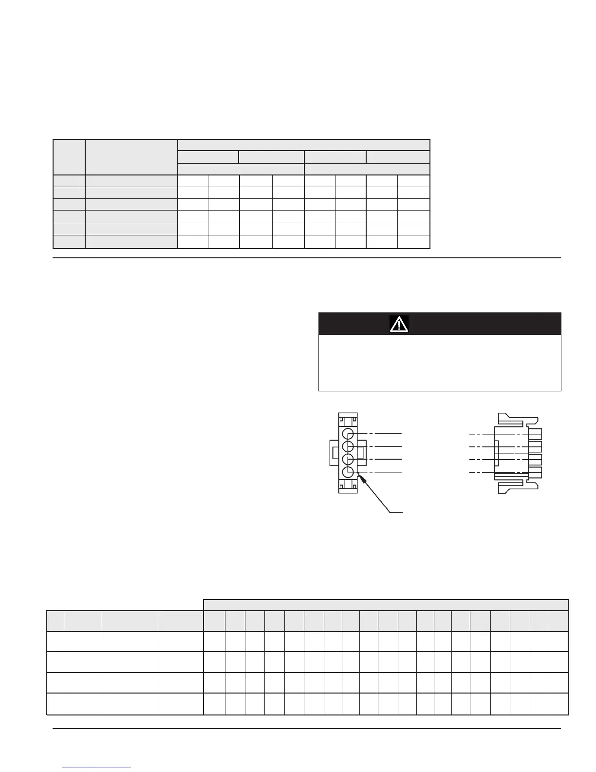
Normally Open (Stem Up) – Push Stem Down to Close
Normally Closed (Stem Up) – Push Stem Down to Open
Note: The actuator spring returns the valve to the stem up posi-
tion when the actuator is de-energized (off)
White/Brown (Stem Up)
Yellow (24 VAC Supply)
Brown (Stem Down)
White (Common)
Locating Rib
Figure 65 - Actuator Wiring
Note: The actuator plug-in wiring
for the Steam Valve is the
same as the Hot Water and
Chilled Water Modulating
Valve. (see gure 65 )
5. Select either a 2-way or 3-way modulating valve. The 3-way
valve is generally selected for diverting water back to the return
main where a constant pump head pressure is required.
CAUTION