Page 38 of 60 IM 817-4
Rigorously adhere to eld wiring procedures regarding proper
lockout and tagout of components.
MicroTech
II™
Remote Wall Mounted Sensor
To avoid electrical shock, personal injury or death:
1. Installer must be qualied, experienced technician.
2. Disconnect power supply before installation to prevent
electrical shock and damage to equipment.
3. Make all connections in accordance with electrical wiring
diagrams, and in compliance with national and local codes.
Use copper conductors only.
4. Do not exceed ratings of the device. This is a low voltage
device: Never apply more than 12VAC/VDC to any lead or
damage will result.
5. Avoid locations where excessive moisture, corrosive fumes,
or vibrations are present.
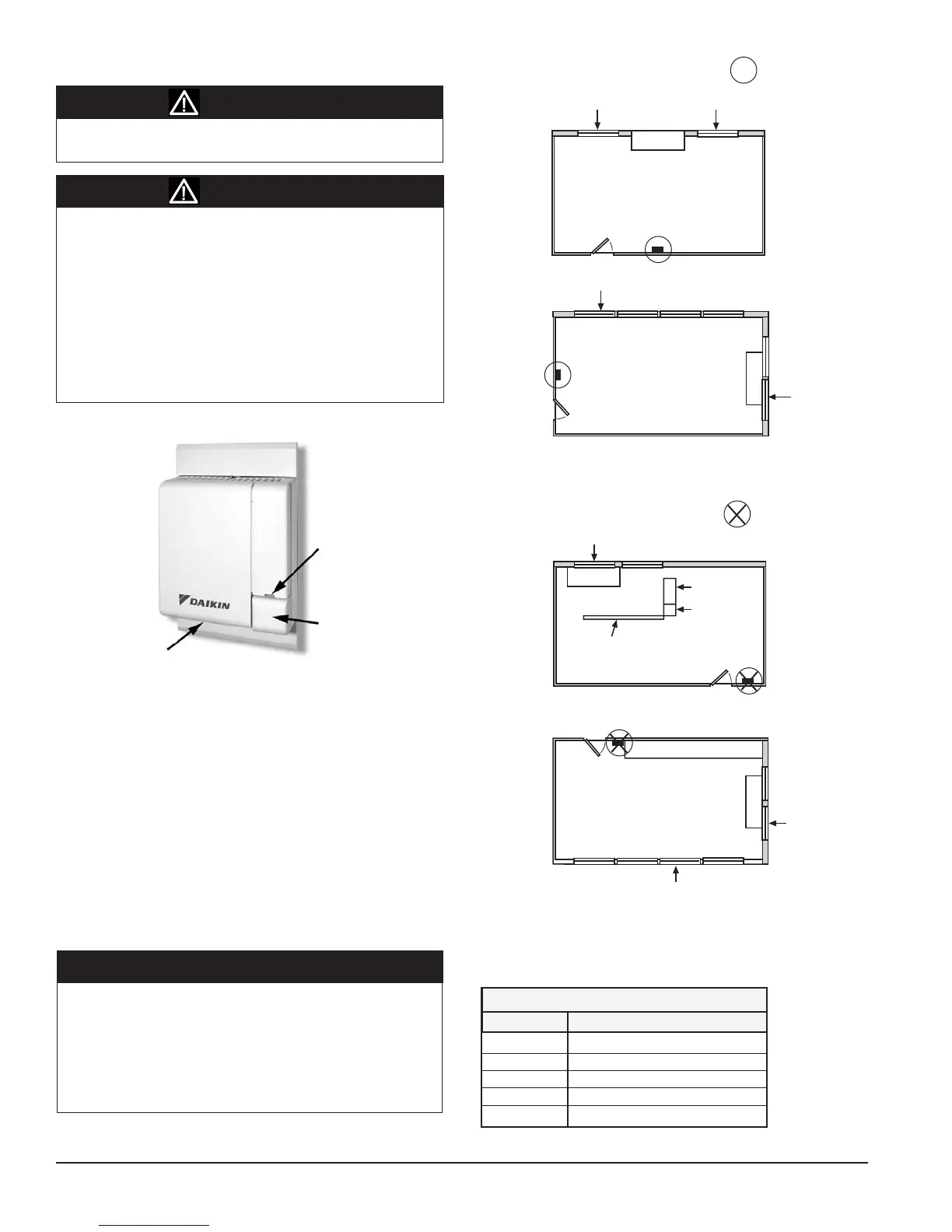
Window Exposure
Window Exposure
Window Exposure
Interior Wall
Interior Wall
Interior Wall
Interior Wall
Unit
Unit
= Correct Sensor Location
Figure 100 - Correct Wall Sensor Locations
Note:
Avoid placing wall sensor near drafty areas such as doors or windows.
Avoid external walls, or dead spots near exposed columns. Avoid
direct sunlight on wall sensor.
Window Exposure
= Incorrect Sensor Location
Window Exposure
Interior Wall
Interior Wall
Window Exposure
Unit
Unit
Interior Wall
Interior Wall
Window Exposure
Cubicle Wall
Shelving
File Cabinet
Shelving
Figure 101 - Incorrect Unit and Wall Sensor Locations
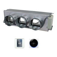
Figure 99 - Basic Remote Wall Sensor
LED
Tenant Override Button
Sensor
All MicroTech II equipped unit ventilators are provided as standard
with a unit mounted space temperature sensor. The unit mounted
temperature sensor is provided with a quick disconnect plug (white)
located outside of box with numbered wires 101 and 102. When
using a remote wall mounted temperature sensor the unit mounted
temperature sensor quick disconnect plug must be separated so
that the unit mounted sensor is disconnected from the UVC.
When Using A Remote Wall Mounted
Temperature Sensor
If a decision is made to use a Remote Wall Mounted Temperature Sensor
instead of the unit mounted room air sensor then placement of the
Remote Wall Mounted Temperature Sensor is critical for proper room
temperaturesensing(seegures100and101).TheUVCiscapableof
using one of three remote wall mounted temperature sensors. Figure
104 shows a 4-wire connection (plus shield drain wire) (see table 25).
It is recommended that additional wires be pulled to compensate for
potential wire breakage or future options. The Basic Wall Mounted
Temperature Sensor requires only 3-wires (plus shield drain wire)
since the Basic Wall Mounted Temperature Sensor has no setpoint
adjustment(seegure103).
Table 25. Max Sensor Wire Length and Gauge
WARNING
WARNING
NOTICE
Maximum sensor wire length for less than 1
o
F error
Gauge Length
14 AWG 800 ft. (244 m)
16 AWG 500 ft. (152 m)
18 AWG 310 ft. (94 m)
20 AWG 200 ft. (61 m)
22 AWG 125 ft. (38 m)