Si01-501 FT09/13DV2S, FT25/35DVM, FT25/35DSG
Removal Procedure 163
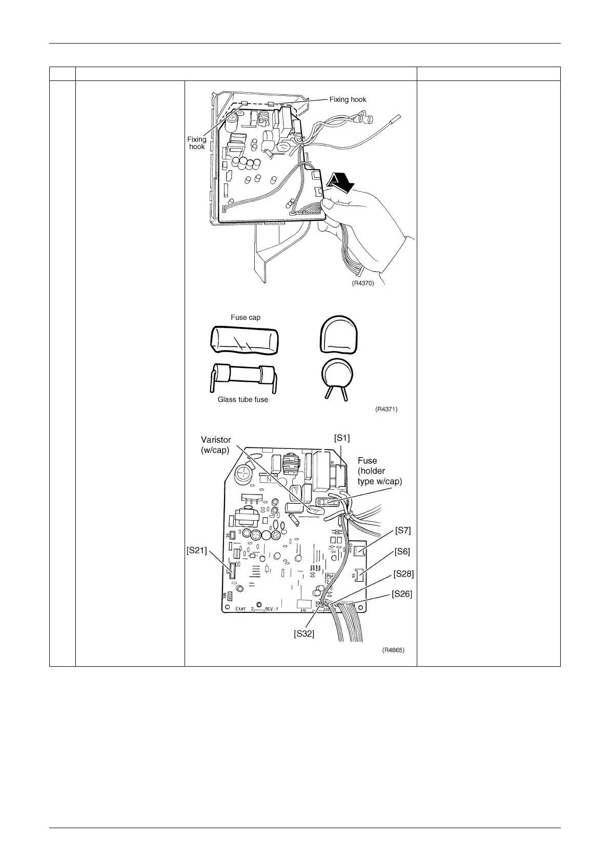
2
Lift up the bottom of the
control PCB and pull it
out.
When mounting the control
PCB, make sure that it is
fixed by upper hooks.
3
The figures show the
names of the PCB
component parts.
Lead-free solder (PbF) is
used for the PCB. When
replacing the PCB, use the
specific solder and soldering
iron.
In case of FT25/35DVM,
FT25DSG, FT09DV2S.
[S1] To AC fan motor
[S6] To swing motor
[S7] To AC fan motor (Hall IC)
[S21] HA connector
[S26] To display PCB
[S28] To signal receiver PCB
[S32] To heat exchanger
thermistor
Step Procedure Points