Printed Circuit Board Connector Wiring Diagram and Name Si18-201
66 Printed Circuit Board Connector Wiring Diagram and Name
1.4 FTK50~60HV Series, FTKD50~71JV Series,
FTX50~60HV Series, FTXD50~71JV Series
Cooling Only FTK50 / 60HVEC, FTKD50 / 60 / 71JVE (A) (9), FTKD50 / 60 / 71JVET
Heat Pump FTX50 / 60HVEC, FTXD50 / 60 / 74JVEA (9), FTXD50 / 60 / 71JVET,
FTXD50 / 60 / 71JV1B
Printed Circuit
Board
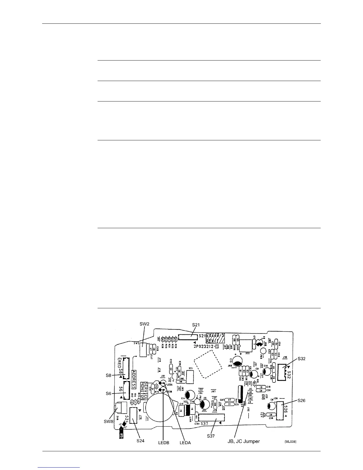
Printed Circuit Board (1) (Control PCB)
Printed Circuit Board (2) (Power Supply PCB)
Printed Circuit Board (3) (Display PCB)
Printed Circuit Board (4) (Signal Receiver PCB)
Name of Connector
Other Designations
Printed Circuit
Board (1)
(Control PCB)
1) S1 Connector for Fan Motor
2) S6 Connector for Swing Motor (Horizontal Flap)
3) S8 Connector for Swing Motor (Vertical Flap)
4) S21 Connector for Centralized Control to 5 Rooms
5) S24 Connector for Display PCB
6) S25, S27, S36 Connector for Control PCB
7) S26 Connector for Signal Receiver PCB
8) S31, S32 Connector for Room Temp/Heat Exchanger Thermistor
9) S37 Connector for Power Supply PCB
1) V1 Varistor
2) SW7 (S1W) Operation Switch
3) SW2 (S2W) Address Switch
4) SW8 (S8W) Cleaning Indicator Reset Switch
5) LED3 (GRN) LED for Operation
6) LED4 (YLW) LED for Timer
7) LED5 (RED) LED for Cleaning
8) LED A, LED B LED for Service Monitor